Tag: Mechanical Integrity

The 2020 Christmas Update

Merry Christmas to our Ammonia Refrigeration Process Safety community!


Well, this year has been interesting, eh? The hits keep coming it seems, and it was no different to those of us in the Process Safety field. Behind the scenes, we’ve been working on a fairly major set of improvements to the PSM system. Originally scheduled for August, we’ve finally managed to push it across the finish line just in time for the Holidays!

Significant improvements were made to the core of the system (The SOPs and ITPMRs) through an unprecedented amount of end-user feedback. Remember, this system relies on the feedback of operators, technicians, service personnel, and Process Safety professionals to improve.

All updated documents have the 122520 date-code, but here’s a run-down:

  • Minor updates to definitions file
  • All element written plans:
    • Where it was appropriate, did a little harmonization with the newest IIAR Process Safety Management & Risk Management Program templates. (There isn’t really anything they cover we don’t, but there are some places we harmonized the phrasing where we cover the same ground)
    • Ensured all element Written Plans refer to the ROSOP QA – Document Quality Control section in the Document Management
    • Minor editing / formatting improvements
  • Minor change to Operator Training element to ensure that Initial Training on Incident Investigation includes a review of recent and routinely recurring incidents.
  • Improvements to the II element written plan’s “Incident Investigation Process Flowchart”
  • SOPs
    • Minor changes to the Implementation Policy: Review and Annual Certification to harmonize with the IIAR guidance
    • Annual SOP Certification letter improved to correlate with the SOP element Written Plan more closely
    • The SOP element Written Plan Implementation Policy: SOP Authoring / Generation section now provides “Best Practices” standard language for warnings, step comments, step instructions, etc.
    • ALL SOP Templates now:
      • Use the “Best Practices” language.
      • Include better language tying them to the ITPMRs
      • Reference ROSOP-PPE in the Safety considerations section
      • Additional Equipment Considerations added to harmonize with the IIAR guidance
    • ROSOP PPE slightly improved with reference to LEO
    • ROSOP LOTO improved with improved language from end-users
    • Minor updates to ROSOP QA – Document Quality Control section.
    • ROSOP LEO streamlined and simplified with a good amount of end-user feedback
    • New ROSOP ITPM based on significant end-user operator input and feedback (See MI section below)
  • MI / ITPMRs
    • All ITPMRs now provided as PDF forms as well as Word documents
    • All ITPMRs have improved references including to the new ROSOP ITPM
    • All ITPMRs now have a space to record task hours
    • All frequency ITPMRs are now in a single document. For example, previously we would have a 30-day, 90-day, and 365-day ITPMR for condensers. Now we have a single ITPMR for condensers with all the items and you simply use the applicable sections. This allowed each step in the ITPMRs to have its own unique step code. This is important because….
    • A new SOP was created called ROSOP ITPM which includes additional information for less-skilled operators and technicians. This new ROSOP also is used as a repository of best-practices and collected knowledge from field operators. Relevant guidance from applicable IIAR standards was also included directly in the SOP where we thought it useful to those performing the MI work. A group of contractor service technicians and end-user operators contributed to the creation of this SOP and We FULLY expect this SOP to grow and improve as we get even more field use and operator feedback.


To implement:

  • Written Plans: Follow the Implementation Policy: Managing Procedure / Document Changes. These should be straight-forward.
  • Definitions file: Replace with the new one
    1. For the new PPE and LOTO templates, either adopt them as-is or incorporate their changes to your existing PPE & LEO SOPs
    2. For all your equipment SOPs, consider updating them to the new language during your next scheduled revision / team review.
    3. For the NEW ROSOP-ITPM and PSSRs see the MI section below
  • MI: Replace the existing ITPMRs with the new ones, providing training that when the CMMS (or other scheduling system) calls for a frequency based ITPMR, just use the equipment specific ITPMR and fill it out to the appropriate frequency.
  • Provide training on the new ROSOP ITPM. Please collect feedback for improvements so we can all improve its performance.

Dealing with non-standard (non-routine) work in your Process Safety program

Occasionally we come across an issue we’ve customarily addressed, but never documented. Put another way: We realize we have a policy – even if an informal one – on how to deal with certain situations, but we’ve never turned that policy into a formal, written one.

It’s incredibly common to have these informal policies in smaller departments, or when a task is rare. You can usually identify them after-the-fact when you are told “That’s just the way we do things here. Everybody knows that.”

When we find these items in our Covered Processes, we should endeavor to document them. Today I’d like to talk about a big one: What do we do when the existing written procedures don’t match with the conditions or situations we are facing in our work. What written guidance are you providing to your Process Operators and Technicians on how to deal with this situation?

Every functioning Operations / Maintenance department has a policy – even if an informal, undocumented one – on how they deal with this issue.  

For years I’ve relied on the text in the SOP Written Plan concerning Temporary Operations:

The ammonia system is not operated in any temporary modes without a written SOP. If a component requires maintenance or replacement, that portion of the system is isolated and removed from service through a written SOP. Other Temporary Operations are handled through the MOC element which will ensure supervisory oversight. Temporary Operation SOPs are often via a written modification of an existing SOP in the form of an addendum.

This worked well, but it was a little bit obscure and (understandably) only thought to apply to SOPs themselves. That needed to change. What we’ve done to our system today, is formalized and documented guidance on how to deal with these non-standard / non-routine situations.

A new policy was placed in the RMP Management System Written Plan…

To ensure integration of this policy, the following text was added to the Operating Procedures (Implementation Policy: Using an SOP – Performing a Procedure, and Implementation Policy: Operating Phases, Temporary Operations) and Mechanical Integrity (Implementation Policy: Mechanical Integrity Procedures or MIPs) element Written Plans: “The Implementation Policy: Non-Standard Work. Addressing Conditions / Situations outside of existing Procedures found in the RMP Written Plan should be used when site/equipment/system Conditions or Situations are found to be different than those anticipated in the exiting written procedures.”

Are you handling non-standard / non-routine work well in your Process Safety program? If you are, and have a better idea, we’re always open to improvements. If you aren’t handling it well, perhaps you can implement the example above? 


For Inside-Baseball type people: This chart was inspired by the API RECOMMENDED PRACTICE 2201 Safe Hot Tapping Practices in the Petroleum and Petrochemical Industries, Chapter 4, Section 4.3.1, Figure 3—Example Decision Process for Authorizing Hot Tapping. Other than genericizing that flowchart to cover all types of work, I also made two large changes:

  • Routed the post “change conditions” step back to the start so we re-evaluate the existing procedure considering changed conditions/situations rather than short-circuiting back to the Management step.
  • Rewrote the flow/wording so that Condition Changes are preferred over mere procedural changes. The thinking was that we should prefer more engineering-type changes over administrative ones, where possible.


IIAR 7-2019 Update

It’s been coming for a while now and yesterday it became official:

Introducing: ANSI/IIAR 7-2019Developing Operating Procedures for Closed-Circuit Ammonia Refrigeration Systems

In 2013, the first issue of IIAR 7 replaced the operations information contained in IIAR Bulletin No. 110, Guidelines for Start-Up, Inspection, and Maintenance of Ammonia Mechanical Refrigerating Systems.

This standard was first approved as an American National Standard by the American National Standards Institute (ANSI) in August 2013. ANSI requires reaffirmation or revision for periodic maintenance requirements of existing standards every five years. Work began on periodic maintenance of this standard in February 2017 and was completed in April 2019.

This standard defines the minimum requirements for developing operating procedures for closed-circuit ammonia refrigeration systems. Informative Appendix A was added to provide explanatory information related to provisions in the standard.


A little over two years ago, the SOP templates were updated to include all the requirements of IIAR 7 2013. That was a pretty large undertaking, but if you already made those changes, it looks like you are in good shape! I’ve reviewed the new IIAR 7 and it turns out we only need to make one substantive change to programs using the current templates.


What’s the requirement / change? 

The 2013 version required a visual inspection of hoses when they were used. This was a pretty minor requirement. The newer version requires that procedures include “Steps to inspect hoses and fittings visually to make sure they are suitable for ammonia refrigeration service”  whenever you Transfer (such as in pump-down) or Charge ammonia. To address this issue, I’ve modified the ROSOP-LEO and Permit form to include an explicit check and a reference to the “ITPMR-AHT-365 – Ammonia Transfer Hose Annual ITPM Record” we recently added due to IIAR 6.

So, if you’ve already updated your system for IIAR 6 compliance, then all you need to do is update your LEO procedure and Permit. If you haven’t updated your system for IIAR 6 compliance, then you need to integrate the new ITPMR as well as make plans to address the entirety of IIAR 6.

Note: Overall the 2019 IIAR 7 is much simpler than the 2013  version. It’s moved a lot of stuff to informative appendices which removes most of my complaints about it. Unfortunately they renumbered* just about every single requirement in the standard. This meant I had to completely renumber / rewrite my standalone SOP audit template. The good news is that the IIAR7-2019 version of that audit was reduced from 110 pages to 87. Of those remaining 87 pages of questions, 60 pages are due to IIAR 7.

* This was not an attempt to drive me closer to insanity, but an attempt to harmonize numbering systems between all the IIAR standards. I know this because I actually asked the IIAR about this. Thankfully, Tony Lundell has a good sense of humor.

IIAR 6 – What do you need to know?

What is IIAR 6?

ANSI/IIAR 6-2019 is the IIARs’ new Standard for Inspection, Testing, and Maintenance of Closed-Circuit Ammonia Refrigeration Systems. To quote the forward from the public review:

This is a new standard intended to replace IIAR Bulletin No. 108 Guidelines for: Water Contamination in Ammonia Refrigeration Systems, IIAR Bulletin No. 109 Guidelines for: IIAR Minimum Safety Criteria for a Safe Ammonia Refrigeration System, IIAR Bulletin No. 110 Guidelines for: Start-Up, Inspection, and Maintenance of Ammonia Mechanical Refrigerating Systems, and IIAR Bulletin No. 116 Guidelines for: Avoiding Component Failure in Industrial Refrigeration Systems Caused by Abnormal Pressure or Shock. This new standard is intended to be a single source for the minimum requirements for ITM tasks for safe closed-circuit ammonia refrigeration systems.

Note: Design items pertaining to Bulletin No. 108 and Bulletin No. 116 are being considered to be incorporated in the next revision of IIAR 2, before these two bulletins are superseded.

When will it take effect?

Now that ANSI/IIAR 6-2019 has finished its Public Reviews, the end of this long journey is nearly over. Already approved by the IIAR Board of Directors  and ANSI, the new standard should be published around July 1st.

Once the new standard is officially published it comes into effect once YOU or the AHJ adopt it. Most model codes are expected to adopt it in their 2021 review cycles.

Why should I care about it now?

There are a few reasons:

  • The old combination of outdated and scattered bulletins was difficult to follow and wasn’t updated to deal properly with modern equipment. ANSI/IIAR 6-2019 has a more modern sensibility.
  • There’s really nothing in ANSI/IIAR 6-2019 you shouldn’t want to do – it’s all fairly sensible “good practice” advice.
  • There’s a slightly lower administrative / MI overhead following the new standard than the old bulletins.
  • I think – overall – that it’s easier to comply with ANSI/IIAR 6-2019 than the old combination of bulletins.


How would I go about ensuring compliance with IIAR 6?

You will have to thoroughly review ANSI/IIAR 6-2019 and perform a Gap Analysis between its requirements and your current PSM/RMP system. Pay special attention to:

  • Your Mechanical Integrity element, schedule, work orders (ITPMRs) and MI procedures.
  • Your SOPs to the extent that they deal with shutdowns, start-ups and turn-arounds.


What would such a Gap Analysis look like?

 If you are using my template system, the good news is that I’ve updated the ENTIRE system to be ANSI/IIAR 6-2019 compliant. Because this has been a LARGE project that’s taken a lot of time, all the new files have been given the same date code: 030219.. You can grab the updated templates on the Google Shared Drive. Some things like the Element Written Plans, ITPMRs are plug-and-play, but others like the MI-EL1, SOPs, etc. will have to be customized for your facility. If (when) you update your PSM/RMP system, don’t forget to implement your MOC procedure! Please note: ALL future template additions will include the ANSI/IIAR 6 compliant text that has been added.

Below is my list of implementation challenges, observations, and changes


Challenge #1: Section 5.5.1.3 Inspection & Test documentation

While I applaud the IIAR for pointing out the necessary requirements for a FUNCTIONALLY EFFECTIVE MI system, it’s a very real possibility that this section and its requirements will be interpreted to require this documentation IN THE MI system. That’s unrealistic for some of the information and experience has shown us that it’s likely unworkable in the field. Below is a table that shows the IIAR documentation requirements and how they are handled in the PSM system.

IIAR Cite

Requirement How it’s Handled
5.1.1.3.1 Date of the inspection or test. OSHA/EPA requirement already handled on ITPMR.
5.1.1.3.2 Name of the individual or individuals that performed the inspection or test. OSHA/EPA requirement already handled on ITPMR.
5.1.1.3.3 Serial number or other identifier of the equipment on which the inspection or test was performed. OSHA/EPA requirement already handled on ITPMR.
5.1.1.3.4 Description of the inspection or test performed. OSHA/EPA requirement already handled on ITPMR.
5.1.1.3.5 Recommended corrective action(s) for each deficiency identified. OSHA/EPA requirement already handled on ITPMR.
5.1.1.3.6 Description of corrective action(s) for each deficiency identified. OSHA/EPA requirement already handled on ITPMR.
5.1.1.3.7 Identification of each designated responsible person assigned and authorized to remedy each deficiency identified. OSHA/EPA requirement. Handled in the Management System master recommendation tracking form RT-1. NOT duplicating this information on MI docs.
5.1.1.3.8 Results based on the conditions at commencement of the inspection or test, including instrumentation readings. This is already covered in the ITMPR Corrective Actions, Recommended Actions & Comments section if implemented correctly.
5.1.1.3.9 Expected activation set points (+/-) including a functional description of the control logic. This information is already provided in the respective equipment RESOPs and system level ROSOPs. Since all our ITPMRs are used in conjunction with the SOPs this should be sufficient.
5.1.1.3.10 Results based on the conditions after completion of the inspection or test, including instrumentation readings. OSHA/EPA requirement already handled on ITPMR.
5.1.1.3.11 Expected completion date(s). OSHA/EPA requirement. Handled in the Management System master recommendation tracking form RT-1. This may be handled through a CMMS, but we’re NOT duplicating this information on our MI docs.
5.1.1.3.12 Actual completion date(s). OSHA/EPA requirement. Handled in the Management System master recommendation tracking form RT-1. This may be handled through a CMMS, but we’re NOT duplicating this information on our MI docs.


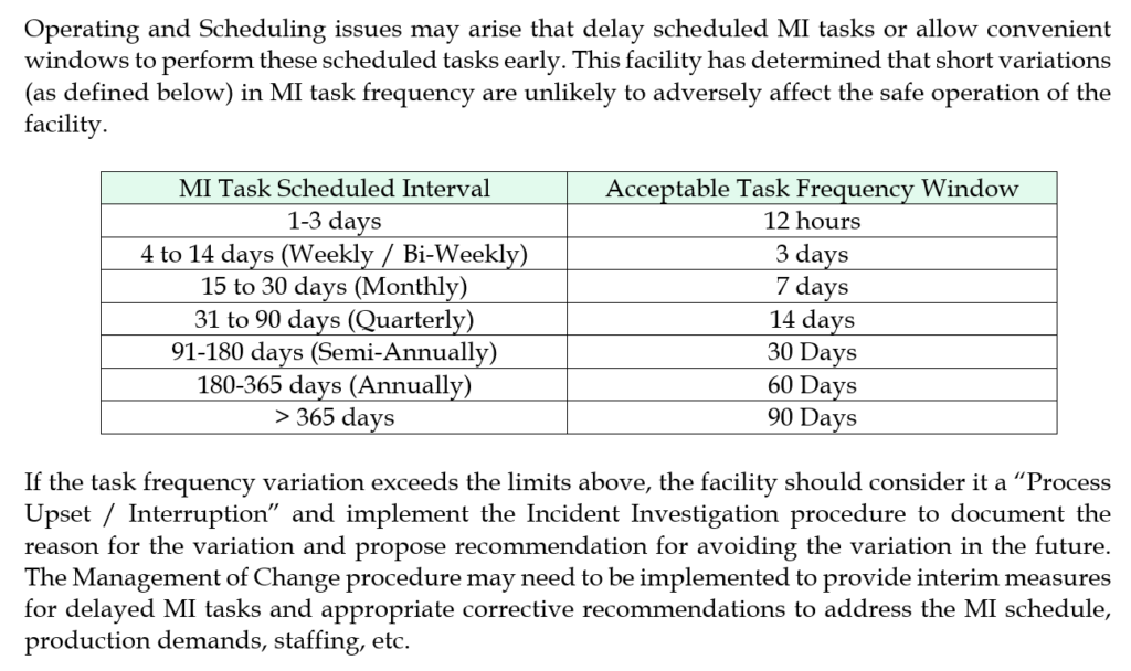
 Challenge #2: Section 5.2, Table 5.2

The IIAR is introducing the same concept here as I did last year with the “Acceptable Task Frequency Window.” I think their window is over-broad and would not be comfortable defending it without further engineering rationale. For example, they are giving a 1 month window on a quarterly task vs. my 14 days, a 2 month window on a semi-annual task vs. my 1 month window. I’m sticking with my more conservative window for now, but – as always – you are welcome to change yours.


Challenge #3: Section 5.2

The IIAR is rightly calling out the need to re-evaluate task frequency based on a history of deficiencies. I’ve incorporated some of their wording directly in the MI Implementation Policy: Mechanical Integrity Schedule as follows: Where a history of repeated deficiencies has been recorded, task frequencies / methods should be re-evaluated. This is usually triggered through the Incident Investigation element and managed through the MOC/PSSR element.

The IIAR is also stating “Where a history of fault-free operation has been recorded, the (ITM) task frequencies are permitted to be decreased.” I am not comfortable with incorporating this wording into the written plan as while it is not necessarily wrong it is extremely difficult to defend without providing significant engineering rationale. OSHA has published a lot of guidance saying the opposite of what the IIAR is saying here, and while I believe OSHA is wrong in their guidance, we should probably pick-and-choose your battles better than this.


Challenge #4: Section 5.3.6

 5.3.6.1 – This section implements a few new logs/documentation requirements, including the “Procedure for Communicating between shifts” that the CCPS has long recommended. Those using the COM-LOG (as outlined in the Employee Participation Written Plan) were already handling this well. To improve the system though, that section has been moved from the EP plan and placed in the RMP (Management System) Written Plan and renamed “Written Communication Log.”

5.3.6.2 requires documentation on secondary coolants. The ITPMR HX-90 & ITPMR HX-365 already does much of this but a new line adds “If any glycol was added / removed, record the type and amount.” While in this section, removed all the references to Glycol and replaced with Fluid so it can be used with Brine and Glycol systems.

5.3.6.3 requires documentation of the NH3 test records. The required information was added to a new ITPMR: ITPMR-NH3 and it was added to the MI-EL-1.

5.3.6.4 requires documentation of the addition / removal of any oil. Created a new log called OIL-LOG and updated all PU, PV & RC ITPMRS to include a reference to this log during oil addition/draining steps.

5.3.6.5 requires documentation of the lubrication type, quantity needed, and quantity used. Created a new log called the LUBE-LOG and updated all AU, HX, EC, RC & VENT ITPMRS to include a reference to this log during lubrication steps.

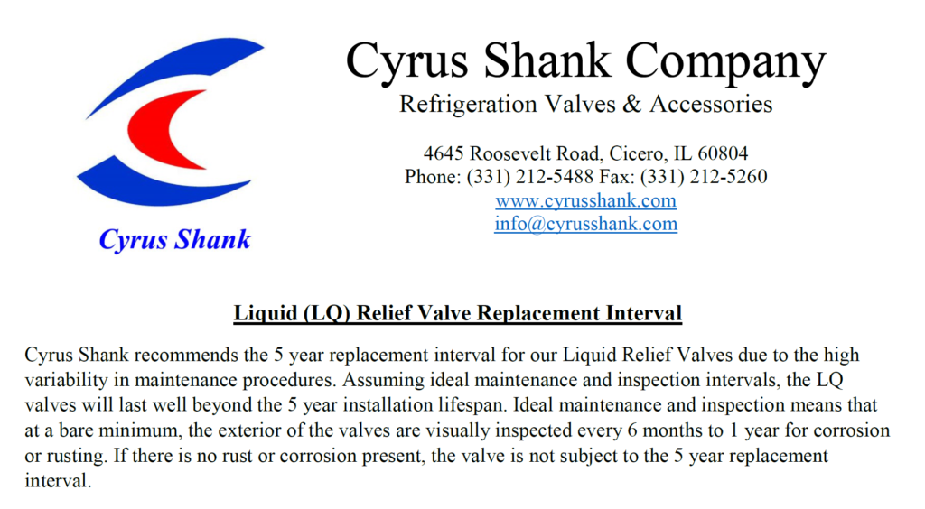
5.3.6.6 requires documentation of Relief Valves. I have no intention of creating a log for this as all the information should be in the PSI and whatever work order / ITPMR was used to replace the relief valve. To make this easier, I’ve included new text in the ITPMR-PRV-365 “If the relief valve is to be replaced, the new valve model number and pressure setting must be confirmed and recorded by TWO people before replacement to be considered a “Direct Replacement.” “In-Kind” and other types of replacements must be handled in accordance with the facility MOC policy.” I’ve also included signature boxes in that ITPMR line item.


Challenge #5: Section 5.3.7

This section deals with record retention requirements. The advice given here by the IIAR does not seem to reflect the RMP and PSM guidance given by the EPA and OSHA and has therefore been skipped. A careful reading of the informative appendix shows that the drafters of this document understood that MI documentation needs to be kept for the life of the process. In any case, we’re in a digital world so you can avoid the argument entirely if you scan the documents, put them on a cloud-based server, and recycle the paper.


Challenge #6: Section 5.4.2

This section replaces the old IIAR B110 5yr Independent Inspection. It includes qualifications & conflict-of-interest requirements. In the informative appendix, they’ve also buried a certification requirement. All these requirements have been added in the Mechanical Integrity Written Plan under the Implementation Policy: Five Year Independent MI Inspection. To make my customer’s lives easier, I’ve also included a Responsible Person certification page in my MI Report Template as well as a signed statement regarding conflict-of-interest signed by the Team Leader for my MI Inspections, PHA’s and Compliance Audits.


Challenge #7: Section 5.5.1

This section deals with calibration of the instruments used in tests and inspections. I have included similar requirements in the ROSOP-QA concerning gauges for a long time, but it’s often ignored. We need to re-emphasize this issue! The ROSOP QA Pressure Gauge section was renamed to Testing Instrument and reworded to cover the additional ANSI/IIAR 6-2019 requirements.

PSM Program / Template Changes: The entire template PSM/RMP program was altered to conform with ANSI/IIAR 6-2019. All changes made in the 030219 templates are outlined below:

ALL PSM / RMP Element Written Plan Changes

  • Moved Definitions from individual element Written Plans References and Definitions Section to a stand-alone document. The stand-alone definitions document was placed in the RMP / Management System binder / folder. The total list of definitions was expanded to cover much of the same ground as IIAR 1 – Definitions. Where the definitions I use varied from the IIAR significantly, I added the IIAR definitions with a “Per IIAR, …” at the end of the definition I’m using. Where IIAR definitions are used, they were updated to the most recent version of IIAR 1. Added the new ANSI/IIAR 6-2019 definitions to the stand-alone definitions document.


RMP / Management System Element Written Plan Changes

  • Moved Implementation Policy: Written Communication Log (COMLOG) from Employee Participation to this Plan. (Not specifically required by ANSI/IIAR 6-2019 but a good idea I’ve wanted to implement for a while)
  • Moved the content of Implementation Policy: PSM Meeting Notes from Employee Participation to this Plan. Also expanded this section to include some suggested agenda items for PSM Team Meetings. (Not specifically required by ANSI/IIAR 6-2019 but a good idea I’ve wanted to implement for a while)


EP PSM / RMP Element Written Plan Changes

  • Renamed Implementation Policy: Communication between Shifts (COMLOG) to Implementation Policy: Written Communication Log (COMLOG) and moved it to the RMP (Management System) Written Plan. (Not specifically required by ANSI/IIAR 6-2019 but a good idea I’ve wanted to implement for a while)
  • Moved content of Implementation Policy: PSM Meeting Notes to Implementation Policy: PSM Team Composition, Meeting Documentation and Agenda in the RMP (Management System) Written Plan. (Not specifically required by ANSI/IIAR 6-2019 but a good idea I’ve wanted to implement for a while)


HW PSM / RMP Element Written Plan Changes

  • Updated both versions of the template to include explicit statement on NOT performing Hot Work or using Sulphur Sticks during Charging, or when removing Oil / NH3 from the system. (IIAR 6 5.6.3.4)


 PSSR PSM / RMP Element Plan Changes

  • Updated ALL the PSSR forms (Word) to match the new 1yr ITPMRs. Maybe someday I’ll create the PDF forms again but it’s a lot of work and I’d rather we all work with the new ITPMRs to validate / field verify them before I expend that effort.
  • Added new ITR-LP-PSSR for non-ammonia Liquid Pumps


MI PSM / RMP Element Written Plan Changes


References and Definitions

  • Added ANSI/IIAR 6-2019 as a standard reference
  • Added IRC MI Guidebook as a standard reference


Implementation Policy: Mechanical Integrity Schedule

  • Slight change to first sentence to clarify that this policy is covering the Ammonia Refrigeration System to cover the same ground as IIAR 6 5.1.1
  • Added language concerning modifying the schedule based on a history of recorded deficiencies.
  • Added IIAR 6 5.2.3 language concerning daily tasks not being required during holidays/weekends.


Implementation Policy: Mechanical Integrity Task Documentation

  • Modified the Corrective Actions, Recommended Actions & Comments section to improve the explanation of what’s expected in the ITPMR forms to cover the same ground as IIAR 6 5.1.1.3.8


Implementation Policy: Access to MIPs and Manufacturer’s Equipment Manuals

  • Modified this section for clarity so that it clearly includes all Process Operators and refrigeration Contractors. Removed specific location wording. (IIAR 6 5.3.2)


MI-EL-1 Maintenance Schedule / Checklist Changes

  • Added a line for Generators / Standby power sources (IIAR 6 5.5.4)
  • Added a line for Ammonia Hoses (IIAR 6 11.1.4, 11.1.5)
  • Changed IIAR B110 references to ANSI/IIAR 6-2019
  • Added Filename / Template Revision to the bottom of the Checklist. (Not specifically required by ANSI/IIAR 6-2019 but a good idea I’ve wanted to implement for a while)


ITMPR Changes


ALL ITPMRS

  • Added color banding. Thanks Scott!
  • Re-organized tasks for more grouping.
  • Set ITPMT tables to repeat Header Row as several ITPMRs are now two pages
  • Standardized (hopefully) the formatting of the numbered / bulleted lists
  • Re-organized the catch-all sections at the end. These are now a little bit longer, but they seem to be easier to read / follow now. Thanks to Scott for the idea.
  • Incorporated some additional items from field feedback. Thanks Jeremiah, Scott & Victor!
  • Added new ITPMR-LP for non-ammonia Liquid Pumps


Note: none of the above are specifically required by ANSI/IIAR 6-2019 but I’ve wanted to implement them for a while.


ITMPR AHT-365, AHNT-365 (Ammonia Hoses)

  • New ITPMRs based on ANSI/IIAR 6-2019 Table 11.1.4 & 11.1.5 to cover Ammonia Hoses (Transfer and Non-Transfer)


ITMPR AC-30, AC-365 (Air Curtains)

  • Added Lube-LOG reference
  • Incorporated IIAR 6 Table 11.1.6 valve items into the annual ITPMRs


ITMPR AP-365 (Ammonia Pumps)

  • Added Lube-LOG reference
  • Incorporated IIAR 6 Table 7.1 items into the ITPMRs
  • Incorporated IIAR 6 Table 11.1.6 valve items into the ITPMRs


ITMPR AU-90, AU-365 (Air Units)

  • Added Lube-LOG reference
  • Incorporated IIAR 6 Table 9.1 items into the ITPMR
  • Incorporated IIAR 6 Table 11.1.6 valve items into the ITPMR


ITMPR DETECT-180 (NH3 Detectors)

  • Incorporated IIAR 6 Table 12.3 items into the ITPMR


ITMPR DT-90, DT-365 (Diffusion Tanks)

  • Reformatting / Renumbering for consistency with other ITPMRs.
  • Added leak / freeze protection checks


ITMPR EC-30, EC-90, EC-365, EC-SD (Evaporative Condensers)

  • Added Lube-LOG reference (EC-90, EC-365, EC-SD)
  • Renumbered EC-90 to EC-180 (MI-El-1, Checklist)
  • Incorporated IIAR 6 Table 8.1 items into the ITPMRs
  • Incorporated IIAR 6 Table 11.1.6 valve items into the ITPMRs


ITMPR HX-90, HX-365 (Heat Exchangers)

  • A new item “If any glycol was added / removed, record the type and amount.”
  • Added Lube-LOG reference
  • Replaced references to Glycol with Fluid so it can be used for Brine systems as well.
  • Incorporated IIAR 6 Table 11.1.6 valve items into the ITPMRs


ITMPR MI-5yr (5yr MI)

  • Incorporated new ANSI/IIAR 6-2019 requirements in the ITPMR


ITMPR MR-365 (Machine Room)

  • Incorporated ANSI/IIAR 6-2019 Table 12.2 items into the ITPMR


ITMPR NH3 (Ammonia)

  • New ITPMR based on IIAR 6 Table 15.1


ITMPR PIPE-365

  • Incorporated IIAR 6 Table 11.1 items into the ITPMRs
  • Incorporated IIAR 6 Table 11.1.6 valve items into the ITPMRs


ITMPR PRV-365 (Pressure Relief Valves)

  • Included new text in the ITPMR-PRV-365 “If the relief valve is to be replaced, the new valve model number and pressure setting must be confirmed and recorded by TWO people before replacement to be considered a “Direct Replacement.” “In-Kind” and other types of replacements must be handled in accordance with the facility MOC policy.” (Not specifically required by IIAR 6 but a good idea I’ve wanted to implement for a while)
  • Included verification signature boxes in the valve replacement ITPMR line item. (Not specifically required by IIAR 6 but a good idea I’ve wanted to implement for a while)
  • Incorporated IIAR 6 Table 11.1.6 valve items into the ITPMR
  • Incorporated IIAR 6 Table 13.1 items into the ITPMR


ITMPR PU-90, PU-365 (Purgers)

  • Combined Hansen and Parker into single ITPMR (Not specifically required by IIAR 6 but a good idea I’ve wanted to implement for a while)
  • Added Oil Drain line and OIL-LOG reference
  • Incorporated IIAR 6 Table 14.1 items into the ITPMRs
  • Incorporated IIAR 6 Table 11.1.6 valve items into the ITPMRs


ITMPR PV-90, PV-365 (Pressure Vessels)

  • Added OIL-LOG reference
  • Added note to “operating within limits” question on PV-365 to remind the user to check pressure and temperature
  • Incorporated IIAR 6 Table 10.1 daily items into the ITPMRs
  • Incorporated IIAR 6 Table 11.1.6 valve items into the ITPMRs


RC-30, RC-90, RC-365 (Refrigeration Compressors)

  • ITMPR Removed RC-30 (MI-El-1, Checklist)
  • Added check that setpoints are appropriate for connected vessels (RC-90, RC-365)
  • Added Lube-LOG reference (RC-90, RC-365)
  • Added OIL-LOG reference (RC-90, RC-365)
  • Incorporated IIAR 6 Table 6.1 items into the ITPMRs
  • Incorporated IIAR 6 Table 11.1.6 valve items into the ITPMR


ITMPR SS-7, SS-365 (Safety Showers)

  • Incorporated IIAR 6 Table 12.5 items into the ITPMRs


ITMPR VENT90, VENT365 (Machine Room Ventilation)

  • Added additional IIAR 2 checks to VENT-365
  • Incorporated IIAR 6 Table 12.1 items into the ITPMRs


SOP (RESOP & ROSOP) Template Changes

All

  • While leak-checking was already addressed to some degree, there was some room for improvement. A leak check reminder has been placed in the LEO Return to Service A leak check task has been placed in ALL equipment SOP steps that open Isolation Valves in the Normal Startup procedural section (IIAR 6 5.5.3)
  • Where it wasn’t already done, all Normal Startup steps re-arranged to ensure that we are opening the unit to the system starting with he lowest threat and working towards the greatest threat: suction -> DC -> hgd -> liquid (Not specifically required by IIAR 6 but a good idea I’ve wanted to implement for a while)
  • For ALL Equipment RESOPS:
    • Slightly reworded Emergency Shutdown section to make it simpler. (Not specifically required by IIAR 6 but a good idea I’ve wanted to implement for a while)
    • Removed any specific MI steps from the Maintenance sections. We’re simply kicking it to the MI-El1, equipment-specific ITPMR’s and IOM’s. (Not specifically required by IIAR 6 but a good idea I’ve wanted to implement for a while)


ROSOP LEO – Line & Equipment Opening

  • Added leak check reminder in Return to Service section.


ROSOP SWT – System Walkthrough

  • Incorporated all ANSI/IIAR 6-2019 tables daily / weekly items into the ROSOP
  • Changed “Engine Room” to “Machine Room” everywhere I could find it! (Not specifically required by IIAR 6 but a good idea I’ve wanted to implement for a while)
  • Harmonized text between the RESOP “Monitor Normal Operations” sections and this document. (Not specifically required by IIAR 6 but a good idea I’ve wanted to implement for a while)
  • Added Autopurgers to Machine Room section


ROSOP QA – Quality Assurance

  • Added a section on Ice Accumulation (IIAR 6 5.6.8)
  • Updated Vessel & Pipe sections to include new guidance on corrosion. (IIAR 6 10.1.1-2)
  • Updated Pipe section to include new guidance on allowable thickness, Table A.11.1.1.3.1 Piping Sizes, Schedules, and Thicknesses (IIAR 6 A.11.1.1.3.1)
  • Updated Vessel section to include new guidance on nameplates. (IIAR 6 10.1.4)
  • Renamed Pressure Gauge section to Testing Instrument and provided additional ANSI/IIAR 6-2019 requirements. (IIAR 6 5.5)


RESOP AP – Autopurger

  • Incorporated Table 14.1 (autopurgers) daily items into the Monitor Normal Operations Section and harmonized that section with the ROSOP SWT Walkthrough procedure.


RESOP AU – Air Unit

  • Incorporated Table 9.1 (evaporators) daily items into the Monitor Normal Operations Section and harmonized that section with the ROSOP SWT Walkthrough procedure.


RESOP C – Compressors

  • Incorporated Table 6.1 (compressors) daily items into the Monitor Normal Operations Section and harmonized that section with the ROSOP SWT Walkthrough procedure.


RESOP EC – Condensers

  • Incorporated Table 8.1 (condensers) daily items into the Monitor Normal Operations Section and harmonized that section with the ROSOP SWT Walkthrough procedure.


RESOP HPRTSR – Non-recirculating Vessels

  • Incorporated Table 10.1 (vessels) daily items into the Monitor Normal Operations Section and harmonized that section with the ROSOP SWT Walkthrough procedure.


RESOP HTR – Recirculating Vessels

  • Incorporated Table 7.1 (pumps) daily items into the Monitor Normal Operations Section and harmonized that section with the ROSOP SWT Walkthrough procedure.
  • Incorporated Table 10.1 (vessels) daily items into the Monitor Normal Operations Section.


RESOP HX – Heat Exchangers

  • Incorporated Table 9.1 (evaporators) daily items into the Monitor Normal Operations Section and harmonized that section with the ROSOP SWT Walkthrough procedure.


Update on the Cyrus Shank LQ Series Relief Valves Replacement Schedule

A little over a year ago, our Process Safety Engineer, Josh Latovich, posted an article entitled “The Cyrus Shank LQ Series Relief Valves – A Discussion on Manufacturer’s Recommendations and the 5 Year Pressure Relief Valve Interval.” The article dealt with confusion surrounding dueling RAGAGEP’s for the replacement interval of hydrostatic valves.

Since that time the issue has come up repeatedly with various opinions provided by industry organizations, end-users, OSHA & EPA inspectors and others. In an October 10th, 2017 update to the article to say “If the Cyrus Shank engineering department changes their position then this issue can be re-evaluated…”

Well, GOOD NEWS. At the 2018 RETA Conference in Dallas, TX this week I was lucky enough to get to spend some time with Cyrus Shank engineer Matt Powell. He was willing to discuss the issue and provide assistance to resolve this issue. Here’s what we need from Cyrus Shank regarding this issue:


This means that the manufacturer is onboard with the IIAR’s position on NOT having to replace these valves if they are visually inspected.

THAT SAID, you still need to look at the FUNCTION of these valves in your system during your Process Hazard Analysis (PHA) to see if their failure will negatively impact your system. In the way they are NORMALLY used, a failure of these valves would cause efficiency issues, rather than safety ones. But you will need to look at the unique situation you have with them before deciding whether a replacement schedule is appropriate or not.

Thanks again to Matt Powell and Cyrus Shank for finally putting this issue to rest. You can download a copy of the letter from them at this link.

For a full recap of the issue, you can go to the original article.

What can we learn from the Fernie Ammonia fatalities?

The October 17th, 2017 Ammonia release in Fernie, BC resulted in three fatalities:

On October 16, 2017, the curling brine chiller at the Fernie Memorial Arena was put back into operation after a seasonal shutdown. During the shutdown and seasonal maintenance, ammonia had been detected in the curling brine system, indicating that the curling brine chiller was leaking… A total of three people were found deceased in the mechanical room: the director of leisure services, the refrigeration operator, and a refrigeration contractor mechanic.


Three people died in a completely avoidable incident. If you want to know the particulars of the incident, I’d recommend you go read the Incident Report itself. While we can’t go back in time and avoid this particular incident, we can extract some valuable lessons from it to prevent a similar incident in the future.

There’s a lot that went wrong, but we’re going to focus on a few key failures in Mechanical Integrity, Process Safety, and Release / Incident Response. We’ll briefly discuss each failure and provide ten opportunities for improving your current Process Safety system.

Note: While this incident occurred in Canada, which does not have robust Process Safety regulation, we’re going to provide our analysis as if it was a PSM/RMP plant. Even if this incident had occurred in the US, the total system inventory was estimated at less than 1,000 pounds, placing it in the General Duty category. Most operators of these General Duty systems do not choose to implement a PSM system – hopefully this incident will cause them to re-evaluate that choice.


Equipment Age and installation: In 2011, the facility received a recommendation from their mechanical contractor to replace the chiller due to its age. It had been in service for about 24 years and had a life expectancy of 20-25yrs. (At the time of failure the chiller was in service for approximately 31yrs.) The facility actually budgeted for this replacement, deferred it, and then dropped the idea altogether. The report (and appendices) detail this decision making and indicates that the people making these decisions didn’t understand the underlying safety issues or the possible repercussions of these decisions. In part this was due to management turnover – the people who received the initial recommendation no longer worked at the facility when those recommendations were due to be implemented. Additionally, post-release, it was determined that the failed coupling was not properly supported.

Possible PSM citations: 1910.119(d)(3)(ii) for not installing the coupling per the manufacturers recommendations. 1910.119(d)(3)(ii) for equipment operating outside manufacturer’s recommended lifespan. 1910.119(e)(1) for the PHA not analyzing the hazards associated with operating outside the manufacturer’s recommended lifespan. 1910.119(j)(5) for operating the equipment with a known (service life) deficiency without assuring safe operation. 1910.119(m)(5) for not addressing and resolving a recommendation. (if the recommendation was made due to an indication of NH3 in the brine)

Opportunity #1: When a piece of equipment has a stated service life, you need to either replace the equipment per the recommendation or support your decision to keep it in service with a suitable engineering rationale.

Opportunity #2: When operators & contractors make recommendations, they need to provide CLEAR and defensible reasons for those recommendations.

Opportunity #3: When recommendations are delayed, deferred, or not completed, the operators & contractors need to ensure that the decision makers understand the implications of their decisions.

Opportunity #4: A Pre-Startup Safety Review (PSSR) and ongoing MI tasks need to ensure that equipment is installed correctly and maintained in a safe manner / arrangement.


Signs of Failure and Deficiency Response: The facility detected NH3 in the brine (by scent) in April of 2017 and then followed it up with a lab test of the brine showing over 3,000ppm of NH3 in June. The facility decided to continue operating the chiller and “monitor” it. A second test in August showed an NH3 concentration near 2,000ppm. Again, the facility decided to keep “monitoring” the situation. The report indicated that the personnel performing the tests and receiving the results didn’t understand the safety implications of them. Even after receiving the tests showing the chiller had failed, the facility decided to keep operating it. According to the report, there was no evidence the facility understood the hazards associated with a leaking chiller.

Furthermore, due to a miscommunication, the contractor believed the facility had taken the chiller out-of-service and they were preparing a bid to replace the leaking unit. The contractor’s recommendation to “monitor” the unit was likely meant to monitor it to see if the valves were leaking by, but the facility interpreted it as a go-ahead to continue operating the defective chiller until it could be replaced as long as they “monitored” it.

The contractor had no policy or procedure in place to deal with a failed chiller outside the usual troubleshooting, repair and replace activities. The investigators concluded that none of the people involved with the decision to continue operating the chiller had training or qualifications involving condition/risk assessment.

Possible PSM citations: 1910.119(j)(5) for operating the equipment with a known (integrity) deficiency without assuring safe operation. 1910.119(m)(5) for not addressing and resolving a recommendation. 1910.119(g)(1)(i) for not training personnel of the hazards associated with a leaking chiller.

Opportunity #5: Personnel reviewing test results need to understand the meaning of the test results and the safety implication of those test results.

Opportunity #6: When test results are provided to decision-makers, these results need to provide adequate information so that the decision-makers understand them and their safety implications.

Opportunity #7: When contractors are called to deal with deficient equipment, they will almost always provide guidance / estimates on how to repair / replace the equipment, but facilities should demand a risk assessment on continued operation of the equipment if they intend to continue its operation while planning and preparing for the repair / replacement.

From Appendix V of the report: “In the majority of instances, owner/operators relied heavily on the refrigeration contractor’s assessment of the equipment and evaluation of the NH3 indication in the brine samples. The owner is accountable for the safe condition and operation of the equipment but in some instances, deferment to the refrigeration contractor’s assessment and recommendations for the equipment was observed.”

Opportunity #8: When a facility outsources maintenance work, they often erroneously think that they are outsourcing the responsibility as well. It is important for a facility to understand that this remains their process and their responsibility. Ask tough questions of your contractors to ensure that you understand the condition of your system.


Facility and Contractor Incident Release Response: On the day of the release at 03:53 the machine room NH3 alarm registered 300ppm. Responding facility personnel observed the brine expansion tank shaking and spilling brine. At 04:30, the facility personnel shutdown the system and closed the chiller suction valve, observing that the shaking in the brine tank stopped. This should have indicated to the facility personnel that the separation between the brine and NH3 sides was completely compromised and that the brine loop was now full of ammonia. At 05:18 the facility personnel called the contractor to come in and re-configure the system to operate without the brine chiller.

At some point during the work, the personnel isolated the brine chiller, trapping the ammonia-laden brine in the chiller with no outlet available for it. As this ammonia-laden brine warmed up, the pressure inside the brine chiller rose and, at an estimated pressure of 30-150psig, a coupling on the brine-side of the brine chiller failed releasing the contents into the machine room and onto the personnel in the room. The estimated total NH3 release was 22 pounds (9lbs immediately vaporizing) resulting in an immediate concentration in the area of 20,000ppm which dissipated to about 5,000ppm over a period of 5 minutes.

The report uses electricity demand to conclude that the personnel did not attempt a pump-out of the brine chiller. Unlike a CSB report, the report does not go into the fatalities. We have no idea where the personnel were positioned in the room, or what – if any – PPE they were wearing at the time of the release. It can reasonably be surmised that they weren’t wearing any respiratory PPE at all.

Possible PSM citations: 1910.119(g)(1)(i) for not training personnel of the hazards associated with NH3 contaminated brine and the hazards of trapping it. 1910.119(h)(3)(ii) for the contractor not being trained in the hazards associated with NH3 contaminated brine and 1910.119(h)(2)(v) for the facility not ensuring this training occurred. 1910.119(n) for not providing “procedures to handle small releases.” 1910.119(f)(1)(i)(D) for not providing an emergency shutdown procedure. 1910.119(f)(1)(i)(E) for not providing an emergency operations procedure.

Opportunity #9: While we often train on the dangers associated with trapping NH3, the dangers of trapping NH3 contamination in a secondary loop is rarely discussed. Operator training in facilities that utilize secondary cooling loops must address contamination and its possible safety implications.

Opportunity #10: While it’s not possible to know for sure, it is extremely likely that all three of these fatalities could have been avoided if the personnel were wearing full-face APRs at the time of release. Note: They would have to have been wearing them, not have them “near-by.” APR’s aren’t magic.


090618 Update: Full WorkSafeBC Incident Report

Updated MI / II Written Plan templates

The Mechanical Integrity and Incident Investigation Written Plans were updated this week to encompass the addition of an Acceptable Task Frequency Window. Essentially, this provides written guidance on task-scheduling slippage. The majority of the change is in the MI element:

Note that this written guidance directs you to the Incident Investigation element if you find that tasks are sliding outside the acceptable window. The only change in that element was to provide this schedule slipping as an example of an event that should be considered a Process Upset/Interruption.

A hat tip to the IRC at the University of Madison Wisconsin for bringing this idea to our attention in their excellent book Principles and Practices of Mechanical Integrity Guidebook for Industrial Refrigeration Systems. We’ve somewhat altered their suggested schedule and our integration into the standard template program wraps it into the Incident Investigation element to deal with those times that our tasks slip outside the acceptable task frequency window. 

As always, the updated Written Plans are available on the shared drive.

Update: Minor change made to the PHA Element Written Plan to correct a numbering issue. Thanks Mindy!

RAGAGEP Hierarchy in Application – A worked example

RAGAGEP (Recognized and Generally Accepted Good Engineering Practices/Principles) is extremely important to our Process Safety programs as it helps define the boundaries of what is (and isn’t) acceptable in our processes and our management of them. There seems to be some confusion in a significant portion of the industry as to how to practically apply RAGAGEP* so I thought a brief discussion (and worked example) might be useful.

Let’s say that we have multiple possible RAGAGEP’s for a single item – such as relief valve replacement schedule. Those multiple RAGAGEP’s may well have differing requirements so we will need to rank them to understand what we actually need to do. Here’s an example RAGAGEP listing from OSHA:

  1. Codes adopted by the AHJ (Authority Having Jurisdiction) such as IMC/UMC
  2. Consensus Standards such as IIAR or ASHRAE
  3. Non-consensus documents such as Pamphlets / Bulletins from industry organizations
  4. Internal Standards such as your corporate policy

What isn’t on that list is manufacturer’s recommendations and there’s a reason why. The things listed above set the RAGAGEP and the manufacturer’s recommendations can modify it.**

There are generally two ways to modify something: make it more or less restrictive.

More: In the event that the manufacturer gives you a recommendation that is more restrictive (conservative) than the RAGAGEP, you must*** accept that more restrictive recommendation.

Less: If the manufacturer gives you a recommendation that is less restrictive than the RAGAGEP, you can accept that less restrictive recommendation, but you will need to document why you believe that the manufacturer’s recommendation is superior to the existing RAGAGEP.

In a recent article, we discussed the replacement schedule for a relief valve that relieves back into the system. The codes reference the consensus standards, which in turn reference some non-consensus bulletins. The bulletin in question, IIAR B110 says that these valves are not subject to the 5yr changeout frequency that other relief valves are. Yet, we have an email from the manufacturer’s engineering department that still recommends the 5yr changeout schedule.

In this case, we have a disagreement between the non-consensus bulletin and the manufacturer’s recommendation. Put another way, we have a generic recommendation on relief valve changeout versus a manufacturer specific recommendation. Obviously, the manufacturer’s specific recommendation on their valves overrides the generic recommendation about all relief valves. Therefore, as long as we are going to use these specific valves, we need to follow the manufacturer’s recommendation. ***

*It’s important to understand that we’re talking about what RAGAGEP decision is the most defensible during an inspection / audit.

** In 1910.119(j)(4)(iii) manufacturer’s recommendations are explicitly called out in conjunction with good engineering practices to set inspection/testing frequency, but the point still holds true.

*** It’s theoretically possible that you can make the engineering case that you know more about the manufacturer’s equipment as it operates in your process than they do, so you can override their recommendation. One method that’s routinely used is to choose an alternative way to achieve the same goals – one where you can show the engineering rationale to prove your alternative is as safe or safer. A common example of that would be replacing the oil based on regular oil analysis rather than changing it out at a specific hour interval. Of course, such a change would have to be thoroughly documented through your Management of Change procedure.

The Cyrus Shank LQ Series Relief Valves – A Discussion on Manufacturer’s Recommendations and the 5 Year Pressure Relief Valve Interval

Many facilities I’ve been to recently use the Cyrus Shank LQ Series valves for internal/liquid relief applications. At these facilities, there tends to be some confusion on the 5-year replacement schedule since these are internal relief valves but still come with a replacement date tag.

Allow me to explain the conflict here:

Back in 2007, the IIAR issued a revision to their Bulletin 110 (Start-up, Inspection and Maintenance of Ammonia Mechanical Refrigerating Systems) which clarified the current standard on replacing or recertifying pressure relief devices. It states that you have 3 options for setting your relief valve replacement schedule:

  1. Every five (5) years from the date of installation. IIAR originally recommended (in 1978) that pressure relief valves be replaced every five years from the date of installation. This recommendation represents good engineering practice considering the design and performance of pressure relief devices; or
  2. An alternative to the prescriptive replacement interval, i.e., five years, can be developed based on documented in-service relief valve life for specific applications using industry accepted good practices of relief valve evaluation; or
  3. The manufacturer’s recommendations on replacement frequency of pressure relief devices shall be followed.

It’s a fairly straightforward list that led to both facilities and manufacturers setting a replacement schedule not to exceed 5 years unless conditions warranted earlier replacement of the devices. The major follow-up question for schedulers is what to do with internal or liquid relief valves, since they’re not usually subject to the same concerns as atmospheric relief valves.

The same IIAR bulletin covers this as an exception to the previous recommendation, stating that:

“Relief devices discharging into another part of the closed-loop refrigeration system are not subject to the relief valve replacement practices.”

Internal relief devices come in many configurations, so relief valves designated for liquid use are normally treated the same as relief regulators or similar devices in that they aren’t replaced until a regular inspection (or system operation) indicates the need.

Generally speaking, when we set our mechanical integrity schedule we first check the standards (IIAR Bulletin 110 in this case) and then modify that schedule based on the manufacturer’s recommendations for our specific equipment. The issue that occurs here is that the Cyrus Shank bulletin issued for their relief valves recommends that they be replaced at least every five years, without specifying which type. After contacting Cyrus Shank, their engineering department responded with the following:

“The cut sheet is a general recommendation that would apply to all of our valves, including the LQ valves. There is one difference between the vapor service valves and the liquid (LQ) ones: the LQ valves have a slightly different sealing ‘surface’ as compared to the vapor. Other than that, they are essentially the exact same in design. The replacement/inspection intervals greatly depend on the nature of the contents and operation of the system so only general recommendations can be given.  We would still recommend the general 5 year replacement interval for both the vapor AND liquid service valves regardless of application. However, the replacement interval is ultimately up to the customer. “

To be consistent with the other justifications in our (manufacturer recommendations based) mechanical integrity schedule, that means that we’ll be replacing those LQ Series valves at least every five years as well. It’s important when setting up a compliant program that we stay informed of all the different RAGAGEP sources that can affect our program. The exception in IIAR Bulletin 110 actually does allow us to set our schedule based on a method of our choosing, but our justification must be defensible. Our defense normally comes from the manufacturer recommendation, so in this case we would have to follow the 5-year recommendation on LQ valves as our RAGAGEP.

10/10/17 Update: Some people have suggested that statements from Cyrus Shank marketing materials somehow override the statements of the Cyrus Shank engineering department. This is absurd and a fundamental misunderstanding of RAGAGEP. If the Cyrus Shank engineering department changes their position then this issue can be re-evaluated, but until then it remains as shown above.

For more on this topic, click here.

11/09/18 Update: Cyrus Shank has helped us deal with this issue!