Tag: RAGAGEP (Page 1 of 3)

Ammonia Process Safety below 10,000 pounds

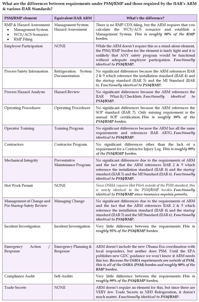
One of the most frequent misconceptions we’ve been dealing with in our industry is a belief that being below the PSM/RMP threshold means you are in some sort of wild-west no-man’s-land where there are no rules. Previously we’ve dealt with that issue in a post called “General Duty vs. PSM/RMP: Is there a benefit to dropping below the 10,000lb threshold?” But that post was really written to people that were considering lowering their NH3 inventory to avoid regulation.

We thought it would be useful to put together an article that dealt with those systems that were already under the PSM/RMP threshold so they better understood the Safety & Regulatory landscape. To that end, we’ve put the information in a executive level 3-page pdf that is easy to email: Ammonia Process Safety below 10k

Email or call us today to have RC&E assist you with all your PSM/RM Program needs! [email protected]    (888) 357-COOL (2665)

Updated IIAR 2-2021 Standard Released

IIAR 2 – 2021 Standard for Design of Safe Closed-Circuit Ammonia Refrigeration Systems has been released by the IIAR and is now available for purchase on their website

The updated standard has several new requirements which resulted in some changes in the PSM/RMP program templates. Here are some of the highlights:

  1. The definitions file was updated with new IIAR 2 definitions. Added in-document headings to skip around the document easily.
  2. The PHA Checklist Template was updated to the new IIAR 2:
    • Added a note that “Provisions for plugs or caps required under IIAR 2 5.9.3.3” on all oil draining plug/cap questions.
    • Added a note that “IIAR 2-2021 5.12.2 requires a check valve during charging” in relevant Charging SOP section.
    • Added a question on Provisions for Pumpout per IIAR 2-2021 5.12.6 on PV1 subsection and all Equipment Subsections.
    • Added/Modified questions on RC1 section about low ambient temperature, and VFD resonance.
    • Added a question on EV2 (Liquid Heat Exchanger) equipment subsection regarding secondary coolant side pressure ratings.
    • Added a question on MR.C Checklist for Classified Space signage.
    • Added a question on PV1 (Piping & Valves) on new MOPD & MSSPD requirements for valves leading to atmosphere.
    • Added a question on PV1 (Piping & Valves) on requirements for unique identification for Emergency Shutoff valves.
    • Modified existing .PSV equipment sub-subsections to include IIAR 2 2021 15.2.6 requirement that liquid relieving reliefs relieve back into the system.
    • Added a note that IIAR 2 2021 13.2.3.1.1 limits carbon steel tubing and carbon steel compression fittings to valve sensing pilots, compressors, compressor packages, and packaged systems to all small-bore piping / tubing questions.
    • Updated MR.C section for new requirements regarding NH3 detection.
    • Updated various checklists (VENT, DET, PSV, DT) to match current IIAR 2-2021 text.
    • Added a new equipment subsection NMR.C for IIAR 2 Equipment located outside of Machinery rooms.
    • Added a new equipment subsection PKG.C for IIAR 2 Packaged Systems and Equipment.
    • Added a new equipment subsection IAC.C for IIAR 2 Instrumentation Controls.
  3. Updated “Contractor Door Sign” to meet new IIAR 2 – 2021 [5.14.1.1] information standards and some ASHRAE 15 – 2019 [11.2.1] standards.

Comments about the changes and the required steps to implement the document changes are present in the “Change Log and Reference” document at 08/02/21.

…Read on further in this post if you want to know about the changes in the new IIAR 2…


Continue reading

Should we perform an Incident Investigation for Hail Damage?

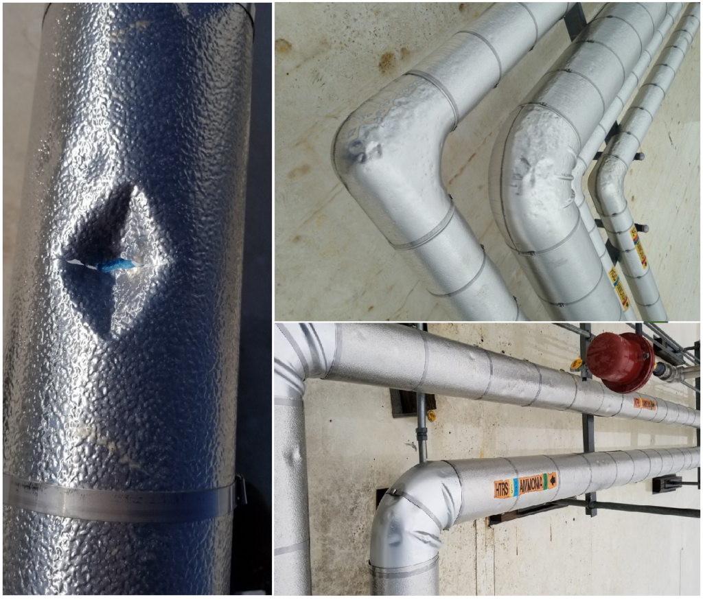
The Issue: Recently an industry friend reached out with a question that I thought was worth sharing. They recently had some fierce storms roll through their area that involved tennis-ball sized hail. This hail caused some insulation damage, but didn’t cause any ammonia release. Here are some pictures of the type of damage they experienced.

Hail Damage pictures

Hail Damage pictures

The question is “Would this require an Incident Investigation?”


The Law: As always, first we look at the law.

OSHA 29CFR1910.119(m)(1): The employer shall investigate each incident which resulted in, or could reasonably have resulted in a catastrophic release of highly hazardous chemical in the workplace.

EPA 40CFR68.81: The owner or operator shall investigate each incident which resulted in, or could reasonably have resulted in a catastrophic release.

While there is obvious damage to the protective jacketing and vapor barrier, you could make a defensible argument that this is not something that could “reasonably have resulted in a catastrophic release of highly hazardous chemical.” That’s not to say there isn’t any value to such an investigation, but that there most likely is not a requirement to investigate this incident based solely on the PSM/RMP rules. But, the rules aren’t the only guidance available to us, so let’s look further.


RAGAGEP and Written Programs: In my opinion, the best RAGAGEP available on the topic is the CCPS book Guidelines for Investigating Chemical Process Incidents, 2nd Edition, which is what inspired the approach we take in our Incident Investigation element Written Plan. Similarly, the IIAR’s publication PSM & RMP Guidelines makes roughly the same types of arguments and include an EPA suggestion that any damage of $50,000 or more should be investigated. If you’ve priced insulation recently, you know we’re likely to hit that threshold.

Here’s the relevant part of our Incident Investigation element Written Plan which incorporates the CCPS guidance:

An Incident is an unusual or unexpected occurrence, which either resulted in, or had the potential to result in:

  • Serious injury to personnel
  • Significant damage to property
  • Adverse environmental impacts
  • A major disruption of process operations

That definition implies three types or levels of incidents:

Accident – An occurrence where property damage, material loss, detrimental environmental impact or human injury occurs. (off-site Ammonia release, product in freezer exposed to ammonia, personnel injury, etc.)

Near Miss – An occurrence when an accident could have happened if the circumstances were slightly different. We sometimes call these incidents “An Accident where something went right”. (Forklift strikes an air unit causing only cosmetic damage and no Ammonia is released, an activation of an automatic shutdown, etc.)

Process Upset / Interruption – An occurrence where the process was interrupted. (Vessel high-level alarm, a nuisance ammonia odor report, ice buildup on an air unit preventing it from cooling properly, failing to conduct required PSM activities as scheduled, etc. Many Process Interruptions are fixed before the event leads to a shutdown. If the equipment was shut down manually or automatically in response to an unexpected occurrence, then the incident is to be investigated as a Near Miss.

This storm damage would seem to trigger the “Significant damage to property” part of the Incident definition and classify it as an Accident due to “property damage.” In accordance with the relevant RAGAGEP and our element Written Plan, we’d expect you to conduct an Incident Investigation despitedefensible argument that the PSM/RMP rules do not require one.


What we accomplish with an Incident Investigation: With a formal assessment of the incident, we’re hoping to document the following:

  1. The safeguards in place were adequate such that an ammonia release did not occur;
  2. The damage was investigated and found to be largely cosmetic with no significant effect on integrity, and limited effect on efficiency;
  3. Provide a documented recommendation to address the damage, both in the long term (replacement/repair) and short-term (sealing up any vapor barrier tears with caulking for example);
  4. Provide a method of tracking the identified corrective actions to closure.

Conclusion: While it seems pretty clear the PSM/RMP rules themselves wouldn’t require an Incident Investigation, RAGAGEP would and there’s much to be gained from one.

IIAR 2 202x Public Review 1

The IIAR has released a proposed draft of IIAR 2 Safety Standard for Design of Closed-Circuit Ammonia Refrigeration Systems for public review. Here’s the notice:

March 20th, 2020

To:

IIAR Members

Re:

First (1st) Public Review of Standard BSR/IIAR 2-202x, Safety Standard for Design of Closed-Circuit Ammonia Refrigeration Systems.

A first (1st) public review of draft standard BSR/IIAR 2-202x, Safety Standard for Design of Closed-Circuit Ammonia Refrigeration Systems is now open. The International Institute of Ammonia Refrigeration (IIAR) invites you to make comments on the draft standard. Substantive changes resulting from this public review will also be provided for comment in a future public review if necessary.

BSR/IIAR 2-202x specifies the minimum safety criteria for design of closed-circuit ammonia refrigeration systems. It presupposes that the persons who use the document have a working knowledge of the functionality of ammonia refrigerating system(s) and basic ammonia refrigerating practices and principles. This standard is intended for those who develop, define, implement and/or review the design of ammonia refrigeration systems. This standard shall apply only to closed-circuit refrigeration systems utilizing ammonia as the refrigerant. It is not intended to supplant existing safety codes (e.g., model mechanical or fire codes) where provisions in these may take precedence.

IIAR has designated the revised standard as BSR/IIAR 2-202x. Upon approval by the ANSI Board of Standards Review, the standard will receive a different name that reflects this approval date.

We invite you to participate in the first (1st) public review of BSR/IIAR 2-202x. IIAR will use the American National Standards Institute (ANSI) procedures to develop evidence of consensus among affected parties. ANSI’s role in the revision process is to establish and enforce standards of openness, balance, due process and harmonization with other American and International Standards. IIAR is the ANSI-accredited standards developer for BSR/IIAR 2-202x, and is responsible for the technical content of the standard.

This site includes links to the following attachments:

The 45-day public review period will be from March 20th, 2020 to May 4th, 2020. Comments are due no later than May 4th, 2020.

Thank you for your interest in the public review of BSR/IIAR 2-202x, Safety Standard for Design of Closed-Circuit Ammonia Refrigeration Systems.

There are MANY proposed changes. I’ll include a full list of the proposed changes at the end of the post, but here are some highlights:

  • Requirements for System Signage became a little simpler
  • Ammonia detection requirements have changed
    • Most installations now need two detectors in a machine room
    • Installation & Testing for detectors outside machine rooms now refer to external RAGAGEPs.
    • “Level 1” detection now requires liquid & hot gas shutoff at 150ppm
    • Requires AHJ approval if not installing ammonia detection in “Areas Other than Machinery Rooms”
  • New requirements for permanently installed Hoses and Corrugated Metal Fittings to ensure they meet ISO 10380 or ARPM IP-14


It’s important that YOU read these changes and make your voice heard if you have any input on them. 


Full change list of the normative sections of the standard below…


Continue reading

RAGAGEP Deficiencies and building a defensible case for an alternative solution

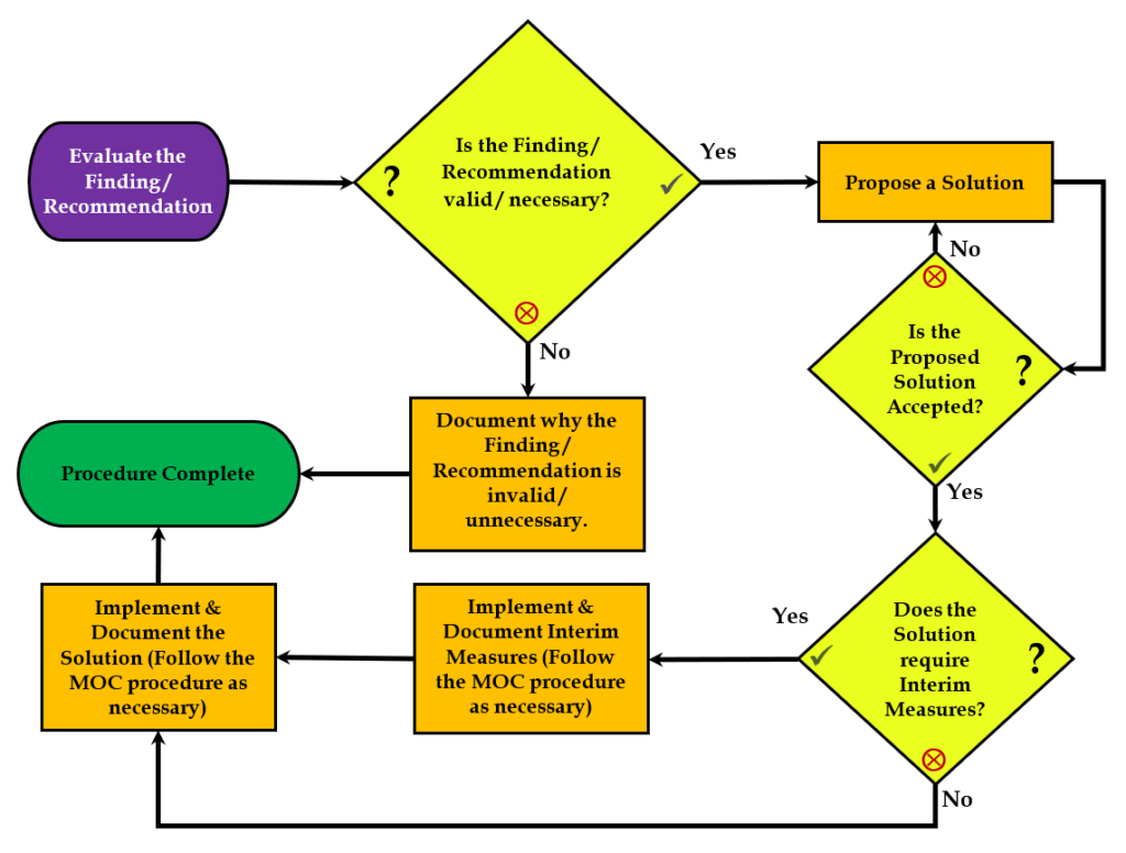
This issue: During a PHA, the facility is using an IIAR 2-2014a checklist and finds that the installation does not meet the requirements of section 6.14.3.3.

6.14.3.3 *Machinery room exhaust shall be to the outdoors not less than 20 ft (6 m) from a property line or openings into buildings.

The distance from the machinery room emergency exhaust outlets on the roof to a rooftop door leading into the building is approximately 8 feet. This is a 1910.119(j)(5) deficiency and a 1910.119(d)(3)(iii) RAGAGEP violation. They have a recommendation to address the issue.

Let’s think about the implications of this issue.


The Analysis: If there was an ammonia leak in the machinery room that activated the emergency ventilation, then the fans would exhaust on the roof very close to this door. In PHA terms, this could be thought of as a “siting” issue.

This situation is pretty rare: only technicians are allowed on the roof, and they are only up there for routine inspections and maintenance. Still, there are two ways the technician could be exposed to this hazard. If they used the door to:

  1. Access the building’s internal stairway from the roof.
  2. Access the roof from the building’s internal stairway.

For situation #1, a release would be easily observed / heard while on the roof in the area of the ventilation fans. There are also other entrances back into the building, including external stairs to the ground level. The team decided this situation was acceptable without any changes.

For situation #2, it would be possible (although not likely due to the noise of the fans) that someone could use the door to access the roof without knowing that they could be exposed to a release on the other side of the door. The team decided this was an unlikely, but possible issue. That is – it’s an unlikely turn of events that a release in the machinery room would occur at the same time as someone would be using the door – but it was possible so it should be addressed.

Obviously, the cleanest solution would be to move either the door or the fans, but that’s not an easy thing to do! Also, it would be a very expensive fix for an issue with such a low probability of occurrence.

The team brainstormed a bit and came up with an alternative plan to address the issue.


The chosen Solution: First, there are only two ways the fans could be exhausting a large amount of NH3 vapor. Either they would me manually operated due to maintenance / leaks or they would be automatically operated due to the IIAR 2-2014a 6.14.7.2.1 required NH3 detection interlock. Either way, a RUN signal is sent to the fan controls and the team decided to install a visual alarm on both sides of the door and use this RUN signal to activate it. Coupled with proper signage and training, the team believes the alarm would provide adequate warning to anyone approaching the door that the emergency ventilation system was running and that the door should not be used.

The team believes this is a defensible solution to non-compliance with IIAR 2-2014a 6.14.3.3. I tend to agree with them – it’s defensible if imperfect.

Perhaps another, actually compliant solution, would be to install ductwork on top of the emergency exhaust fans to raise the exhaust point so the distance from them to the door would meet the 20-foot requirement. Of course, such a change would require a new ventilation calculation to ensure the additional restriction caused by the duct work didn’t pose a problem. This ducting solution would likely be a bit expensive and that could mean that it would take some time to implement. If this duct solution was chosen,  the earlier “alarm” idea would be an excellent interim measure until approval and construction of the ducting project occured.

Note: This 20’ requirement appears to show up first in IIAR 2-2008a effective August 2010. Previously the requirement was a vaguer “13.2.3.11 The discharge of air shall be to the atmosphere in such a manner as to not cause inconvenience or danger.”

Hot Work – NFPA 51B–2019 and Magic Rooms

RAGAGEP is always changing and we have to ensure that our safety programs evolve to match the new / changed requirements. Tuesday I took a dive into NFPA 51B 2019, the standard for “Fire Prevention during Welding, Cutting, and Other Hot Work.” After reading through it, some changes were made to my base program. Here’s the section from my running “Change Log”

092419 – Updated both versions Hot Work Written Plans to deal with NFPA51B-2019.

  • Changed NFPA references to match new section numbers
  • Changed fire watch to 60-minute minimum per NFPA.
  • Updated master definitions file (in \01-RMP\ ) to include updated definition of Fire Watch and new definitions for Fire Protection System and Fire Monitoring.

To Implement:

  • Change out \01 – EPA RMP\Definitions – Glossary of Terms and Acronyms with 092419 version by using the appropriate MOC procedure.
  • Replace \09 – Hot Work\09 – Hot Work Permit Element Written Plan with 092419 version by using the appropriate MOC procedure.
  • Train all personnel involved in Hot Work about new 60-minute fire watch requirement. Document training per the written plan.


This is a fairly simple change. You may have noticed that there is a new section in the “Change Log” for each entry – a “To Implement” section that tells you how to modify your program if it was written based on the baseline templates. I’ve gone back through the last month’s changes and added this information. Time willing, I might do the same for the previous 100+ entries!

While we are on the subject of Hot Work though, I want to bring up another common issue: “Designated Areas.” This is a particularly “Hot” topic right now, because a recent large industrial fire was caused by Hot Work and some people are saying it was an oil fire caused by Hot Work done in a “shop.”

Designated Areas: Many plants have “Designated Areas” such as maintenance or welding shops where Hot Work is conducted without the use of a permit. It should be noted that nothing in the PSM/RMP or OSHA General Industry rules (as interpreted through 1910.119(k)) appear to support this. For this reason, we’ve always called these areas “Magic Rooms” because people seem to think that these rooms are exempt from OSHA rules. The custom actually comes from NFPA 51B:

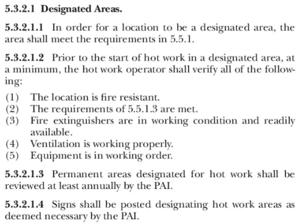
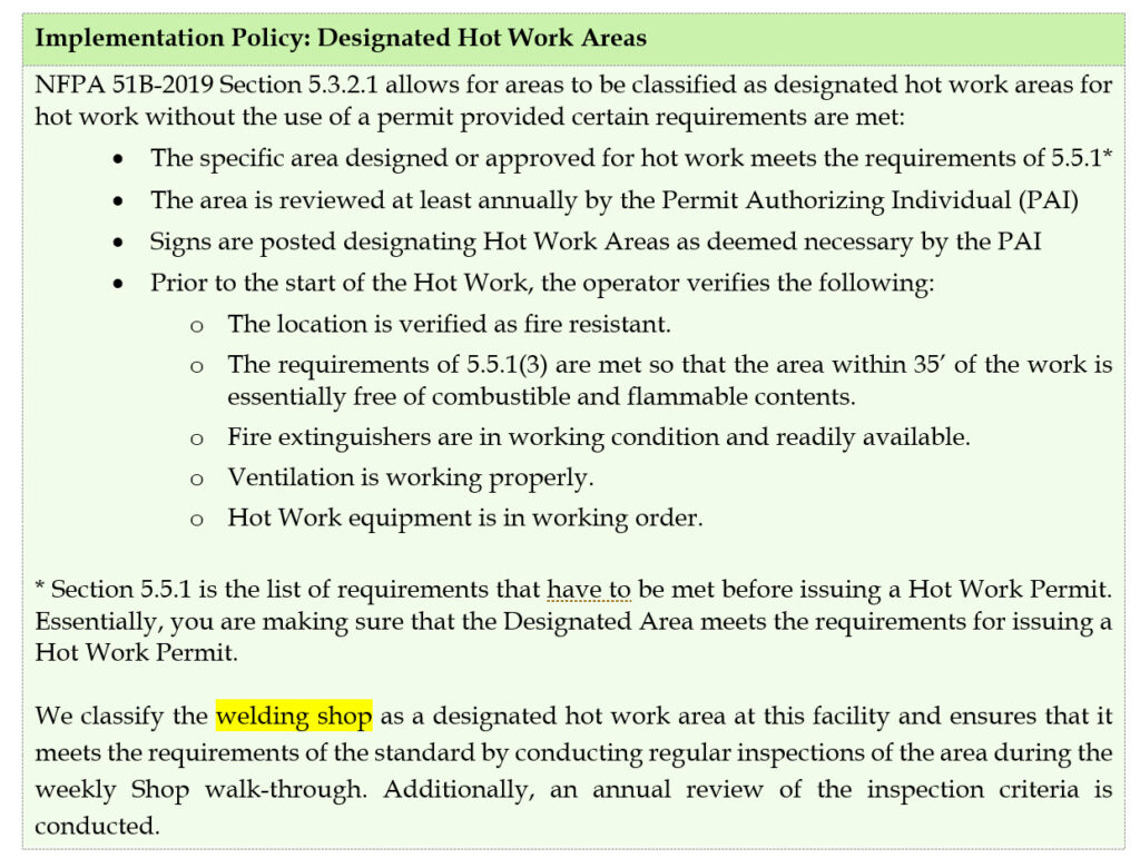
In the 2019 version, it is section 5.3.2.1 which allows for areas to be classified as Designated Hot Work areas. These areas would allow Hot Work without the use of the written permit provided certain requirements are met:

  • The specific area designed or approved for Hot Work meets the requirements of 5.5.1*
  • The area is reviewed at least annually by the Permit Authorizing Individual
  • Signs are posted designating Hot Work Areas
  • Prior to the start of the Hot Work, the operator verifies the following:
    • The location is verified as fire resistant.
    • The requirements of 5.4.2(3) are met so that the area is essentially free of combustible and flammable contents.
    • Fire extinguishers are in working condition and readily available.
    • Ventilation is working properly.
    • Hot Work equipment is in working order.

* Section 5.5.1 is the list of requirements that have to be met before issuing a Hot Work Permit. Essentially, you are making sure that the Designated Area meets the requirements for issuing a Hot Work Permit without actually issuing one.

The acceptability of this custom is in question due to a statement made by OSHA in their PSM Preamble:

“…this proposed provision would not require a permit for Hot Work operations in a welding shop unless the welding shop was located in a process area covered by the standard. OSHA believes that such a location would not exist.” (OSHA, PSM Preamble, 1992)

OSHA was clearly thinking of Petroleum and Chemical plants in that quote, where such situations are usually not found. As of 2019, we are not aware of any Ammonia Refrigeration PSM-covered facility receiving a Hot Work citation for Designated Areas if they follow the requirements of NFPA 51B Section 5.3.2.1. Still, it would be far more defensible if you issued Hot Work permits for all Hot Work, even that work conducted in maintenance and welding shops.


Here’s a look at the Hot Work element Written Plan section dealing with Designated Hot Work Areas:

Note: Previous discussion on Hot Work at this link. You can read the 2019 version of NFPA-51B in its entirety at NFPA.org


IIAR 2 2014 Addendum A

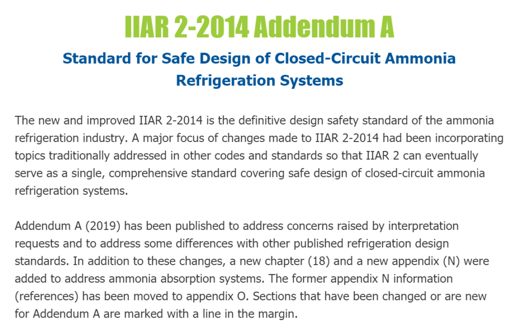
The IIAR has just released IIAR 2-2014 Addendum A:

  • While there isn’t a whole lot that’s changed in the document (compared to IIAR 2-2014) quite a bit of it was re-numbered / re-organized. Based on my review, there’s not too much going on in the new edition:
  • Inclusion of absorption systems
  • Water % allowed in NH3 became more reasonable
  • Significant change to the wording concerning the “corrosion allowance” for vessels such that it is optional now
  • Some equipment hydrostatic protection now points to the “Mechanical Code” rather than the IIAR 2 section 15.6
  • A clearer requirement for pumpout provisions for all equipment
  • Minor clarifications and reorganizations.

I’ve already updated the PHA checklist blanks (and my internal compliance audit template) to reflect the new RAGAGEP.

Here’s my list of changes (which may not be complete) if you are interested in this sort of thing!


Section Requirement in IIAR 2-2014 Requirement in IIAR 2-2014a
1.2 Scope *Scope. Stationary closed-circuit refrigeration systems utilizing ammonia as the refrigerant shall

comply with this standard. This standard shall not apply to

1.      Ammonia absorption refrigeration systems.

2.      Replacements of machinery, equipment, or piping with functional equivalents.

3.      Equipment and systems and the buildings or facilities in which they are installed that existed prior to the legal effective date of this standard. Such equipment, systems, and buildings and facilities shall be maintained in accordance with the regulations that applied at the time of installation or construction.

*Scope. Stationary closed-circuit vapor compression and absorption refrigeration systems utilizing anhydrous ammonia as the refrigerant shall comply with this standard. This standard shall not apply to:

1.      Replacement of machinery, equipment, or piping with functional equivalents.

2.      Equipment and systems and the buildings or facilities in which they are installed that existed prior to the legal effective date of this standard. Such equipment. Systems, and building and facilities shall be maintained in accordance with the regulations that applied at the time of installation or construction.


Note: Absorption systems added to appendix

4.2 Permissible Equipment Locations 4.2.1 Listed Equipment. Listed equipment containing not more than 6.6 lb (3 kg) of ammonia and

installed in accordance with the listing and the manufacturer’s instructions shall be permitted in any occupancy without a machinery room.

4.2.1 Listed Equipment. Listed equipment containing not more than 6.6 lbs (3 kg) of ammonia and installed in accordance with the listing and the manufacturer’s instructions shall be permitted in any occupancy without a machinery room. Listed equipment for use in laboratories with more than 100 ft2 (9.3m2) of floor area is permitted to contain any amount of ammonia if the equipment is installed in accordance with the listing and the manufacturer’s installation instructions.
4.2 Permissible Equipment Locations 4.2.2. *Outdoor Installations. Ammonia refrigeration machinery shall be permitted to be installed outdoors. Ammonia refrigeration machinery, other than piping, installed outdoors shall be located not less than 20 ft from building openings, except for openings to a machinery room or openings to an industrial occupancy complying with Section 7.2. 4.2.2 *Outdoor Installations. Ammonia refrigeration machinery shall be permitted to be installed outdoors when installed in compliance with sections 7.2.2, 7.2.4, 7.2.6, 7.2.7 and 7.2.8. Ammonia refrigeration machinery, other than piping, installed outdoors shall be located not less than 20 ft. from building openings, except for openings to a machinery room or openings to an industrial occupancy complying with Section 7.2.


EXCEPTIONS:

1.      Packaged absorption systems for residential and commercial occupancies with refrigerant quantities not exceeding 22 lbs. (10 kg.) are permitted to be installed within 20 ft. of building openings.

2.      Packaged vapor compression systems for commercial occupancies with refrigerant quantities not exceeding 22 lbs. (10 kg.) are permitted to be installed within 20 ft. of building openings.

3.      Packaged absorption or vapor compression systems with refrigerant quantities such that a complete discharge would not exceed a concentration of 300 ppm in any room or area in which the refrigerant could enter. The calculation procedure shall be in accordance with Chapter 5, Section 5.3.

4.2 Permissible Equipment Locations No Exceptions Listed 4.2.4 EXCEPTIONS:

1.      Listed packaged vapor compression or absorption systems, with no refrigerant containing parts that are joined in the field by other than mating valves that permit sections of the system to be joined before opening the valves, installed in areas or rooms that are not public hallways or lobbies and with refrigerant quantities equal to or less than 6.6 lbs. (3 kg) are permitted for residential occupancies.

2.      Listed packaged vapor compression or absorption systems, with no refrigerant containing parts that are joined in the field by other than mating valves that permit sections of the system to be joined before opening the valves, installed in areas or rooms that are not public hallways or lobbies and with refrigerant quantities equal to or less than 22 lbs. (10 kg) are permitted for commercial occupancies.

3.      Listed, sealed packaged vapor compression or absorption systems with no refrigerant containing parts that are joined in the field by other than mating valves that permit sections of the system to be joined before opening the valves, installed in public hallways or lobbies and with refrigerant quantities equal to or less than 3.3 lbs. (1.5 kg) are permitted for residential and commercial occupancies.

5.2 Anhydrous Ammonia Specifications Table 5.2.2 Purity Requirements

Ammonia Content 99.95% minimum

Non-Basic Gas in Vapor Phase 25 ppm maximum

Non-Basic Gas in Liquid Phase 10 ppm maximum

Water 33 ppm maximum

Oil (as soluble in petroleum ether) 2 ppm maximum

Salt (calculated as NaCl) None

Pyridine, Hydrogen Sulfide, Naphthalene None

Table 5.2.2 Purity Requirements

Ammonia Content 99.95% minimum

Water 50 ppm minimum, 5000ppm maximum

Oil 50 ppm maximum

Salt None

Pyridine, Hydrogen Sulfide, Naphthalene None

5.5 System Design Pressure Note: This item was not present in IIAR 2-2014. It was inserted after 5.5.1.1 which required renumbering 5.5.5.1.3 & 5.5.1.4 to 5.5.1.4 & 5.5.1.5 5.5.1.2 Limited Charge Systems. When parts of a limited charge system are protected from overpressure by a pressure relief device, the design pressure of the protected parts need not exceed the set-pressure of the relief device. The set pressure of the relief device shall not exceed the design pressure of the protected parts.
5.5 System Design Pressure 5.5.1.4 Connecting to Existing Low-Pressure Equipment. Where new low-pressure side

equipment is connected to an existing system that was in operation prior to the adoption of this standard by the AHJ, the design pressure of the new low-pressure side portion of the system shall be permitted to equal the design pressure of the

existing low-pressure side.

5.5.1.5 Connecting to Existing Low-Pressure Equipment. Where new low-pressure side equipment is connected to an existing system that was in operation prior to the adoption of this Standard by the AHJ, the design pressure of the new low-pressure side portion of the system shall be permitted to equal the design pressure of the existing low-pressure side. All other requirements of this standard shall apply.
5.5 Purging 5.8 *Purging. Means shall be provided to remove air and other noncondensable gases from the

refrigeration system.

5.8 *Purging. Means shall be provided to remove air and other non-condensable gases from the refrigeration system. Discharge piping for purging systems that discharge to the atmosphere shall conform to sections 13.4 for support, 15.4.3 for materials, and 15.5.1.2 through 15.5.1.7 for termination.


EXCEPTION: A means for purging is not required for packaged vapor compression and absorption systems with refrigerant quantities that do not exceed 22 lbs. (10 kg.).

5.12 Service Provisions 5.12.4 Pressure Gauges. Where a pressure gauge is installed on the high side of the refrigeration

system, the gauge shall be capable of measuring and displaying not less than 120% of the

system design pressure.

16.4.2 Pressure Gauges. High Side Installation. Where a pressure gauge is installed on the high side of the refrigeration system, the gauge shall be capable of measuring and displaying not less than 120% of the system design pressure.


Note: Basically, it just moved.

5.12 Service Provisions 5.12.5 *Service Isolation Valves. Serviceable equipment shall have manual isolation valves.


EXCEPTION: Packaged systems and portions of built-up systems shall be permitted to have

pump-down arrangements that provide for the removal or isolation of ammonia for servicing

one or more devices in lieu of isolation valves.

5.12.4 *Service Isolation Valves. Serviceable equipment and control valves shall have manual isolation valves. Where multiple pieces of serviceable equipment are readily isolated by a single set of hand isolation valves, the use of a single set of valves meets the intent of this section.
5.12 Service Provisions Appears to be NEW


5.12.5 *Equipment Pumpout. Provisions for pumpout of equipment and control valves shall be provided for maintenance and service.
5.13 Testing 5.13.2 Ultimate Strength. Pressure-containing equipment shall comply with Sections 5.13.2.1 and 5.13.2.2.


EXCEPTION: The following shall be permitted to comply with Section 5.13.2.3 in lieu of

complying with this section:

1.      Pressure vessels.

2.      Piping, including valves, evaporators, condensers, and heating coils with ammonia as the working fluid, provided they are not part of the pressure vessel.

3.      Pressure gauges.

4.      Refrigerant pumps.

5.      Control mechanisms.

5.13.2 Ultimate Strength. Pressure-containing equipment shall comply with Sections 5.13.2.1 and 5.13.2.2.


EXCEPTIONS: The following shall be permitted to comply with Section 5.13.2.3 in lieu of complying with Sections 5.13.2.1 and 5.13.2.2.:

1.      Piping, including valves, evaporators, condensers, and heating coils with ammonia as the working fluid, if they are not part of a pressure vessel.

2.      Pressure gauges.

3.      Control mechanisms.

5.13 Testing 5.13.2.3 Equipment designed based on the exception to Section 5.13.2 shall be required to

comply with additional requirements in Chapter 8 through Chapter 16 and ASME B31.5, as applicable.

5.13.2.3 Equipment and piping designs based on the exception to Section 5.13.2 shall be required to comply with additional requirements in ASME B31.5 as applicable.
5.14 Signage, Labels, Pipe Marking, and Wind Indicators Appears to be NEW – addition required re-ordering the rest of the 5.14 sections 5.14.2 *NFPA 704 Placards. Buildings and facilities with refrigeration systems shall be provided with placards in accordance with NFPA 704. For equipment located outdoors, the placard shall display the following degrees of hazard: Health-3, Flammability-1, Instability-0. For equipment located indoors, the placard shall display the following degrees of hazard: Health-3, Flammability-3, Instability-0
5.17 General Safety Requirements Appears to be NEW – addition required re-ordering the rest of the 5.17 sections *Vessel Pumpdown Capacity. Liquid ammonia shall not occupy a vessel at a volume large enough to create a risk of hydrostatic overpressure unless the vessel is protected by a hydrostatic pressure relief device.


Note: A.5.17.4 The maximum volume of liquid in vessels has traditionally been considered 90% at a temperature of 90°F. Calculations can be done to determine other levels and worst-case temperatures.

5.17.5 Used Equipment This appears to have moved from Section 6.8 5.17.10 Electrical Safety – Electrical equipment and wiring shall be installed in accordance with the Electrical Code.
6 Machinery Rooms 6.3.3.2 Manually operated isolation valves identified as being part of the system emergency shutdown procedure shall be directly operable from the floor or chain operated from a permanent work surface. Emergency valve identification shall comply with Section 5.14.5 6.3.3.2 Manually operated isolation valves identified as being part of the system emergency shutdown procedure shall be directly operable from the floor or chain operated from a permanent work surface. Emergency valve identification shall comply with Section 5.14.4
6 Machinery Rooms 6.6.3 Pipe Marking. Piping shall be marked as required by Section 5.14.5. 6.6.3 Pipe Marking. Piping shall be marked as required by Section 5.14.6.
6 Machinery Rooms 6.7.1 General. Each machinery room shall have access to a minimum of two eyewash/safety shower units, one located inside the machinery room and one located outside of the machinery room, each meeting the requirements in Section 6.7.3. Additional eyewash/safety shower units shall be installed such that the path of travel in the machinery room is no more than 55 ft to an eyewash/safety shower unit. 6.7.1 General. Each machinery room shall have access to a minimum of two eyewash/safety shower units, one located inside the machinery room and one located outside of the machinery room, each meeting the requirements in Section 6.7.3.
6 Machinery Rooms 6.7.2 – Path of Travel. The path of travel within the machinery room to at least one eyewash/safety shower unit shall be unobstructed and shall not include intervening doors. 6.7.2 Path of Travel. The path of travel within the machinery room to at least one eyewash/safety shower unit shall be unobstructed and shall not include intervening doors. Additional eyewash/safety shower units shall be installed such that the path of travel in the machinery room is no more than 55 ft to an eyewash/safety shower unit. The path of travel to at least one eyewash/safety shower unit located outside of the machinery room shall be within 55 ft. of the principle machinery room door. The path of travel shall be unobstructed and shall not include intervening doors.
6 Machinery Rooms 6.8.1 General. Electrical equipment and wiring shall be installed in accordance with the Electrical Code. 6.8.1 Hazardous (Classified) Locations. Electrical equipment and wiring shall be installed in accordance with the Electrical Code. Machinery rooms shall be designated as Unclassified Locations, as described in the Electrical Code, where the machinery room is provided with emergency ventilation in accordance with Section 6.14.7 and ammonia detection in accordance with Section 6.13.


A machinery room not provided with emergency ventilation shall be designated as not less than a Class I, Division 2, Group D Hazardous (Classified) Location, and electrical equipment installed in the machinery room shall be designed to meet this requirement.

6 Machinery Rooms 6.8.2 Machinery rooms shall be designated Ordinary Locations, as described in the Electrical Code, where the machinery room is provided with emergency ventilation in accordance with Section 6.14.7 and ammonia detection in

accordance with Section 6.13.

Machinery rooms not provided with emergency ventilation shall be designated as not less than a Class I, Division 2, Group D Hazardous (Classified) Location, and electrical equipment installed in the machinery room shall be designed to meet this requirement.

6.8.3 Design Documents. Electrical design documents shall indicate whether the machinery room is designated as an Ordinary Location or as a Hazardous (Classified) Location. Where the machinery room is designated as a Hazardous (Classified) Location, the Class, Division, and Group of the electrical classification, as required by the Electrical Code, shall be indicated in the documentation.
6 Machinery Rooms 6.8.2 Design Documents. Electrical design documents shall indicate whether the machinery room is designated as an Ordinary Location or as a Hazardous (Classified) Location. Where the machinery room is designated as a Hazardous (Classified) Location, the Class, Division, and Group of the electrical classification, as required by the Electrical Code, shall be indicated in the documentation. * Moved up one section
6.14 Ventilation “6.14.3.1 Mechanical exhaust ventilation systems shall be automatically activated by ammonia leak detection in accordance with Section 6.13 or temperature sensors and shall be manually operable.” Appears to have been removed. These requirements are already elsewhere in the document so there is no real effect other than requiring 6.14.3.2-6 to be renumbered to 6.14.3.1-5.
6 Machinery Rooms 6.15.1 *NFPA 704 Placards. Buildings and facilities with refrigeration systems shall be provided with placards accordance with NFPA 704 and the Mechanical Code. 6.15.1 NFPA 704 Placards. A NFPA 704 placard shall be provided in accordance with Section 5.14.2 on or next to all doors through which a person can enter the machinery room.
6 Machinery Rooms Appears to be NEW – Just a reminder about earlier requirements


6.15.4 Emergency Control Switch Signage. Signage shall be provided near the emergency stop and emergency ventilation control switches as described in section 6.12.
7 Equipment in Non-Machinery Rooms 7.2.7 Illumination of Equipment Areas. See Section 5.17.6. 7.2.7 Illumination of Equipment Areas. See Section 5.17.7.
7 Equipment in Non-Machinery Rooms Appears to be NEW 7.2.10 Electrical Classification. Areas in compliance with 7.2.1 through 7.2.9 shall be designated as Unclassified electrical locations as described in the Electrical Code, unless a different electrical classification is required by in the space other than for the ammonia refrigeration system.
7 Equipment in Non-Machinery Rooms 7.3.2 Outdoor Systems. Where a refrigeration system or equipment is located outdoors more than 20 ft (6.1 m) from building entrances and exits and is enclosed by a penthouse, lean-to, or other open structure, natural ventilation shall be provided in accordance with this Section 7.3.2 or

mechanical ventilation shall be provided in accordance with Section 6.14 and Section 7.3.1.2.

7.3.2 Outdoor Systems. Outdoor systems include those that comply with Section 4.2.2. For outdoor systems, natural ventilation shall be provided in accordance with this Section or mechanical ventilation shall be provided in accordance with Section 6.14 and Section 7.3.1.
8 Compressors 8.2.2 *Positive-Displacement Compressor Protection. Where a stop valve is provided in the discharge connection, a positive-displacement compressor shall be equipped with a pressure relief device to prevent the discharge pressure from increasing to more than 10% above the lowest maximum allowable working pressure of the compressor or any other equipment located in the discharge line between the compressor and the stop valve, or in accordance with Section 15.3.7, whichever is larger. 8.2.2 *Positive-Displacement Compressor Protection. Where a stop valve is provided in the discharge connection, a positive-displacement compressor shall be equipped with a pressure relief device to prevent the discharge pressure from increasing to more than 10% above the lowest maximum allowable working pressure of the compressor or any other equipment located in the discharge line between the compressor and the stop valve, or in accordance with Section 15.3.8, whichever is larger.
8 Compressors 8.2.6 Rotation Arrow. If rotation is one direction only, a rotation arrow shall be cast in or permanently attached to the compressor frame using an attached label or plate or equivalent means. 8.2.6 Rotation Arrow. If rotation is one direction only, a rotation arrow shall be cast in or permanently attached to the compressor.
10.4 Shell-and-Tube Condensers 10.4.1.5 Where the secondary coolant inlet and outlet piping of shell-and-tube condensers can be automatically isolated, protection from hydrostatic overpressure shall be in accordance with Section 15.6. 10.4.1.5 Where the secondary coolant inlet and outlet piping of shell-and-tube condensers can be automatically isolated, protection from hydrostatic overpressure shall be in accordance with the Mechanical Code.
10.4 Shell-and-Tube Condensers 10.4.2 Procedures/Testing. Shell-and-tube condensers shall be strength tested to a minimum of 1.1

times the design pressure, subsequently leak tested, and proven tight at a pressure not less than

design pressure by the manufacturer.

10.4.2 Procedures/Testing. Shell-and-tube condensers shall be strength tested to a minimum of 1.1 times the design pressure when they are not manufactured as a pressure vessel or shall be pressure tested in accordance with ASME B&PVC, Section VIII, Division 1 when they are manufactured as a pressure vessel. In either case, they shall be subsequently leak tested, and proven tight at a pressure not less than design pressure by the manufacturer
10.5 Plate Heat Exchange Condensers 10.5.1.5 Where the nonrefrigerant process fluid inlet and outlet lines of plate packs can be automatically isolated, they shall be protected from hydrostatic overpressure in

accordance with Section 15.6.

10.5.1.5 Where the non-refrigerant process fluid inlet and outlet lines of plate packs can be automatically isolated, they shall be protected from hydrostatic overpressure in accordance with the Mechanical Code.
10.5 Plate Heat Exchange Condensers 10.5.2 Procedures/Testing. Plate heat exchanger condensers shall be strength tested to a minimum of 1.1 times the design pressure, subsequently leak tested, and proven tight at a pressure not less than design pressure by the manufacturer. 10.5.2 Procedures/Testing. Plate heat exchanger condensers shall be strength tested to a minimum of 1.1 times the design pressure when they are not manufactured as a pressure vessel or shall be pressure tested in accordance with ASME B&PVC, Section VIII, Division 1 when they are manufactured as a pressure vessel. In either case, they shall be subsequently leak tested, and proven tight at a pressure not less than design pressure by the manufacturer.
10.6 Double- Pipe Condensers 10.6.1.5 Where the secondary coolant inlet and outlet piping of double-pipe condensers can

be automatically isolated, they shall be protected from hydrostatic overpressure in

accordance with Section 15.6.

10.6.1.5 Where the secondary-coolant inlet and outlet piping of double-pipe condensers can be automatically isolated, they shall be protected from hydrostatic overpressure in accordance with the Mechanical Code.
11.3 Shell-and-Tube Evaporators Appears to be NEW 11.3.1.1.2 Ultimate strength shall be in accordance with section 5.13.2.
11.3 Shell-and-Tube Evaporators (Ammonia in Shell) 11.3.1.1.2 Pressure vessels coupled to shell-and-tube evaporators shall comply with

Chapter 12.


Note: Renumbered do to Ultimate Strength addition

11.3.1.1.3 Pressure vessels coupled to shell-and-tube evaporators shall comply with Chapter 12.
11.3 Shell-and-Tube Evaporators (Ammonia in Tubes) 11.3.2.1 Design 11.3.3 Design
11.3 Shell-and-Tube Evaporators (Ammonia in Tubes) 11.3.2.1.1 Minimum design pressure shall be in accordance with Section 5.5. 11.3.3.1.1 Minimum design pressure shall be in accordance with Section 5.5.
11.3 Shell-and-Tube Evaporators (Ammonia in Tubes) Appears to be NEW 11.3.3.1.2 Ultimate strength shall be in accordance with section 5.13.2.
11.3 Shell-and-Tube Evaporators (Ammonia in Tubes) 11.3.2.1.2 Pressure vessels coupled to shell-and-tube evaporators with ammonia in the tubes shall comply with Chapter 12. 11.3.3.1.3 Pressure vessels coupled to shell-and-tube evaporators with ammonia in the tubes shall comply with Chapter 12.
11.3 Shell-and-Tube Evaporators (Ammonia in Tubes) 11.3.2.1.3 Where the tube-side inlet and outlet lines of shell-and-tube evaporators with ammonia in tubes can be automatically isolated, the tube side shall be protected from hydrostatic overpressure in accordance with Section 15.6. 11.3.3.1.4 Where the tube-side inlet and outlet lines of shell-and-tube evaporators with ammonia in tubes can be automatically isolated, the tube side shall be protected from hydrostatic overpressure in accordance with Section 15.6.
11.3 Shell-and-Tube Evaporators (Ammonia in Tubes) 11.3.2.1.4 The tube side shall comply with ASME B31.5 or ASME B&PVC, Section VIII, Division 1. 11.3.3.1.5 The tube side shall comply with ASME B31.5 or ASME B&PVC, Section VIII, Division 1.
11.3 Shell-and-Tube Evaporators (Ammonia in Tubes) 11.3.2.2 Procedures/Testing. Shell-and-tube evaporators shall be strength tested to a minimum of 1.1 times the design pressure, subsequently leak tested, and proven tight at a pressure not less than design pressure by the manufacturer. 11.3.3.2 Procedures/Testing. Shell-and-tube evaporators shall be strength tested to a minimum of 1.1 times the design pressure when they are not manufactured as a pressure vessel or shall be pressure tested in accordance with ASME B&PVC, Section VIII, Division 1 when they are manufactured as a pressure vessel. In either case, they shall be subsequently leak tested, and proven tight at a pressure not less than design pressure by the manufacturer.
11.3 Shell-and-Tube Evaporators (Ammonia in Tubes) 11.3.2.3 Equipment Identification… 11.3.3.3 Equipment Identification…
11.3 Shell-and-Tube Evaporators (Ammonia in Tubes) 11.3.2.4 Installation Considerations. Where design permits servicing of evaporator tubes at their installed location, clearance shall be provided as necessary to accommodate maintenance and replacement. 11.3.3.4 Installation Considerations
11.3 Shell-and-Tube Evaporators (Ammonia in Tubes) Requirement given its own number 11.3.3.4.1 Where design permits servicing of evaporator tubes at their installed location, clearance shall be provided as necessary to accommodate maintenance and replacement.
11.4 Plate Heat Exchanger Evaporators 11.4.1.5 Where the nonrefrigerant process fluid inlet and outlet lines of plate packs can be isolated, they shall be protected from hydrostatic overpressure in accordance with Section 15.6 on the process side. 11.4.1.5 Where the non-refrigerant process fluid inlet and outlet lines of plate packs can be isolated, they shall be protected from hydrostatic overpressure in accordance with the Mechanical Code on the process side.
11.4 Plate Heat Exchanger Evaporators 11.4.2 Procedures/Testing. Plate heat exchanger evaporators shall be strength tested to a minimum

of 1.1 times the design pressure, subsequently leak tested, and proven tight at a pressure not

less than design pressure by the manufacturer.

11.4.2 Procedures/Testing. Plate heat exchanger evaporators shall be strength tested to a minimum of 1.1 times the design pressure when they are not manufactured as a pressure vessel or shall be pressure tested in accordance with ASME B&PVC, Section VIII, Division 1 when they are manufactured as a pressure vessel. In either case, they shall be subsequently leak tested, and proven tight at a pressure not less than design pressure by the manufacturer.
11.5 Scraped (Swept) Surface Heat Exchangers 11.5.2 Procedures/Testing. Scraped (swept) surface heat exchangers shall be tested in accordance with ASME B&PVC, Section VIII, Division 1, but at a minimum, shall be strength tested to a minimum of 1.1 times the design pressure, subsequently leak tested, and proven tight at a

pressure not less than design pressure by the manufacturer.

11.5.2 Procedures/Testing. Scraped (swept) surface heat exchangers shall be strength tested to a minimum of 1.1 times the design pressure when they are not manufactured as a pressure vessel or shall be pressure tested in accordance with ASME B&PVC, Section VIII, Division 1 when they are manufactured as a pressure vessel. In either case, they shall be subsequently leak tested, and proven tight at a pressure not less than design pressure by the manufacturer.
11.6 Jacketed Tanks. 11.6.2 Procedures/Testing. Jacketed tanks shall be tested in accordance with ASME B&PVC, Section VIII, Division 1, but at a minimum, shall be strength tested to a minimum of 1.1 times the design pressure, subsequently leak tested, and proven tight at a pressure not less than

design pressure by the manufacturer.

11.6.2 Procedures/Testing. Jacketed tanks shall be strength tested to a minimum of 1.1 times the design pressure when they are not manufactured as a pressure vessel or shall be pressure tested in accordance with ASME B&PVC, Section VIII, Division 1 when they are manufactured as a pressure vessel. In either case, they shall be subsequently leak tested, and proven tight at a pressure not less than design pressure by the manufacturer.
12. Pressure Vessels 12.2.6 *In applications where pressure vessels are subject to external corrosion, the vessels shall be designed and specified with a minimum of 1/16 in. (0.16 cm) corrosion allowance. The external corrosion allowance is in addition to the minimum vessel thickness as required by

ASME B&PVC, Section VIII, Division 1.

12.2.6 * In applications where vessels are subject to external corrosion as determined by the owner or owner’s designated agent, suitable means shall be used to address vessel protection.
14.1 General (Packaged Systems) 14.1.3 *‍Packaged systems shall be ventilated based on the intended operation of the equipment, as specified by the manufacturer. In addition, emergency mechanical ventilation shall be provided where required by any of the following:


1. Package systems located in machinery rooms shall be included as machinery room equipment. Emergency ventilation for machinery rooms shall be in accordance with Section 6.14.

2. Package systems located indoors and outside of a machinery room in accordance with Section 4.2.3, Item 5, shall comply with Section 7.3.1.

3. Package systems located outside that are designed for human occupancy shall comply with Section 7.3.2. Package systems located outside that are not designed for human occupancy shall not require ventilation.

14.5 Ventilation. Ventilation for packaged system shall comply with the following:

1.      Packaged systems that are required to be located in a machinery room as determined in Chapter 4 shall comply with Section 6.14.

2.      Packaged systems located indoors and permitted to be located in areas other than a machinery room in accordance with Section 4.2.3., item 5, shall comply with section 7.3.1.

1.      3. Packaged systems located outdoors shall comply with Section 7.3.2.


Note: Moved and condensed a bit

14.1 General (Packaged Systems) 14.1.4 Equipment and devices incorporated into packaged systems shall comply with the applicable

provisions of Chapter 8 through Chapter 17.

14.1.3 Equipment and devices incorporated into packaged systems shall comply with the applicable provisions of Chapter 8 through Chapter 17.
14.1 Design (Packaged Systems) 14.2.6 *‍Access shall be provided for manually operated valves. Isolation valves identified as being

part of system emergency shutdown procedures shall comply with Section 6.3.3.1 and valve

tagging shall comply with Section 5.14.3.

14.2.6 *Access shall be provided for manually operated valves. Isolation valves identified as being part of system emergency shutdown procedures shall comply with Section 6.3.3.1 and valve tagging shall comply with Section 5.14.4.
14.1 Design (Packaged Systems) 14.2.7 Pipes shall be marked in accordance with Section 5.14.5. 14.2.7 Pipes shall be marked in accordance with Section 5.14.6.
14.1 Design (Packaged Systems) 14.2.8 Equipment shall be labeled in accordance with Section 5.14.2. 14.2.8 Equipment shall be labeled in accordance with Section 5.14.3.
14.1 Alarms (Packaged Systems) 2.      Package systems located indoors and outside of a machinery room, as permitted by Section 4.2, shall be provided with Level 2 detection and alarms in accordance with Section 17.7.2. 3.      Packaged systems located indoors and permitted to be located in areas other than a machinery room, in accordance with Section 4.2.3, shall be provided with detection and alarms complying with Section 7.2.3 or 7.3.1.
14.1 Alarms (Packaged Systems) 3.      Package systems located outdoors that are not  intended for human occupancy shall not require ammonia detection or alarms. 4.      Packaged systems located outdoors that comply with the free-aperture requirements of Section 7.3.2 shall not require ammonia detection or alarms.


5.      Packaged systems located outdoors that do not comply with the free-aperture requirements of section 7.3.2 shall be provided with detection and alarms complying with section 6.13 or if permitted by section 4.2.3 shall be provided with detection and alarms complying with Section 7.3.1

15 Overpressure Protection Devices VARIOUS Note: This whole section was renumbered and partially reorganized. I’m limiting this section to the new or changed requirements.
15.1.2 Overpressure Protection Devices General Appears to be NEW 15.1.2 It is permitted to protect system piping and equipment from overpressure through unobstructed piping that is connected to pressure vessels equipped with overpressure protection. Vessels and equipment that relieve into the system must comply with sections 15.3.7 and 15.3.8.
15.1.3 Overpressure Protection Devices General Appears to be NEW 15.1.3 Rupture discs are not permitted as the only means of pressure relief. They are permitted to be used in series with pressure relief valves and in accordance with 15.2.6.
15.1.4 Overpressure Protection Devices General Appears to be NEW 15.1.4 Fusible plugs are not permitted for use as pressure relief devices.
15.2.1 Pressure Relief Devices Appears to be NEW 15.2.1 Pressure relief devices shall be direct-pressure actuated or pilot operated. Pilot-operated pressure relief valves shall be self-actuated, and the main valve shall automatically open at the set pressure. If the pilot valve fails, the main valve shall discharge at its full-rated capacity.
15.2.3 Pressure Relief Devices Appears to be NEW


15.2.3 – Pressure relief devices shall not use cast iron seats or discs.
15.3 ASME pressure vessels and Non-ASME equipment 15.2.7.1 …Resetting of a pressure relief device shall be performed by the manufacturer or a company holding a valid testing certificate for this work. 15.2.8.1 – …Calibration and set pressure adjustments to pressure relief devices shall be performed by the relief device manufacturer or a company holding a certification for this work.
15.3 ASME pressure vessels and Non-ASME equipment 15.3.1 Pressure vessels and other types of equipment built and stamped in accordance with ASME B&PVC, Section VIII, Division 1, shall be provided with certified pressure relief protection. 15.3.1.1 Pressure vessels and equipment built and stamped in accordance with ASME B&PVC, Section VIII, shall be provided with pressure relief protection in accordance with the ASME B&PVC, Section VIII, Division 1
15.3 ASME pressure vessels and Non-ASME equipment 15.3.2 Pressure vessels intended to operate completely filled with liquid ammonia and capable of being isolated by stop valves from other portions of a refrigeration system shall be protected with a certified hydrostatic service relief device as required by ASME B&PVC Section VIII, Division 1. Hydrostatic overpressure relief shall comply with Section 15.6. 15.3.1.2 – *Refrigerant containing equipment not built in accordance ASME BPVC, Section VIII, and having any single ammonia-containing section exceeding 0.5 ft3 of internal volume shall be provided with pressure relief protection that is in accordance with the ASME B&PVC Section VIII, Division 1.


EXCEPTION: The following types of equipment are not required to have overpressure protection unless it is required by other sections of this standard:

1.      Compressors, pumps, controls, headers, piping, evaporator coils, and condenser coils

2.      Equipment built in accordance with ASME B31.5

3.      Equipment listed by a nationally recognized testing laboratory

15.3 ASME pressure vessels and Non-ASME equipment Appears to be NEW


15.3.2 – Tube and Fin or microchannel evaporator and condenser coils that are located within 18” of a heating source and capable of being isolated shall be fitted with a pressure relief device that discharges according to the provisions of this chapter. The pressure relief device shall be connected at the highest possible location of the heat exchanger or piping between the heat exchanger and its manual isolation valves.


EXCEPTION: Pressure relief protection is not required on tube and fin or microchannel evaporator and condenser coils that are designed for 110% of ammonia’s saturation pressure when exposed to the maximum heating source temperature.

15.3 ASME pressure vessels and Non-ASME equipment 15.3.8 *‍Where combustible material is stored within 20 ft (6.1 m) of a pressure vessel that is outside of a machinery room, the relief device capacity factor, f, in the formulas shall be increased to f = 1.25 (f = 0.1). 15.3.9 *Where combustible material is stored or installed within 20 ft (6.1 m) of a pressure vessel, the relief device capacity factor, f, in the formulas shall be increased to f = 1.25 (f = 0.1).
15.4 Pressure Relief Device Piping 15.4.5 – Where piping in the system and other equipment required to comply with this section could contain liquid ammonia that can be isolated from the system during operation or service, the installation shall comply with Section 15.6 for protection against overpressure due to thermal hydrostatic expansion. * Removed as new items elsewhere address equipment specifically and existing items makes this redundant.
15.4 Pressure Relief Device Piping 15.4.7 – Atmospheric relief piping shall be used only for relieving vapor from refrigerant relief devices or fusible plugs. Relief piping shall not be used to relieve discharge from hydrostatic overpressure relief devices or any other fluid discharges, such as secondary coolant or oil. 15.4.6 – Atmospheric relief piping shall be used only for relieving vapor from refrigerant relief devices. Different refrigerants shall not be vented into a common relief piping system unless the refrigerants are included in a blend that is recognized by ASHRAE Standard 34. Relief piping shall not be used to relieve discharge from hydrostatic overpressure relief devices or any other fluid discharges, such as secondary coolant or oil.
15.5 Discharge from Pressure Relief Devices Appears to be NEW


15.5.1.7 – Piping discharging to atmosphere shall have a provision to mitigate the entry of rain or snow into the discharge piping.
15.6 Equipment and Piping Hydrostatic Overpressure Protection Appears to be NEW


15.6.1 *Protection Required. Protection against overpressure due to thermal hydrostatic expansion

of trapped liquid ammonia shall be provided for equipment and piping sections that can be

isolated and can trap liquid ammonia in an isolated section in any of the following situations: …5. During the shipping of any pre-charged equipment.

16. Instrumentation and Controls 16.1.2 Operating Parameter Monitoring. Instruments and controls shall be provided to indicate operating parameters of the refrigeration system and equipment and provide the ability to manually or automatically control the starting, stopping, and operation of the system or equipment. The instruments and controls shall provide notice if the system’s critical operating

parameters, as determined by the owner or operator, have been exceeded.

16.1.2 *Operating Parameter Monitoring. Instrumentation and controls shall be provided to indicate operating parameters of the refrigeration system and equipment and provide the ability to manually or automatically control the starting, stopping, and operation of the system or equipment. The instruments and controls shall provide notice to an owner’s representative if the system’s critical operating parameters, as determined by the owner or operator, have been exceeded. Monitoring of parameters is permitted to be automatic or manual or a combination of both methods.
16. Instrumentation and Controls 16.1.7 Ultimate Strength. The pressure-containing envelope maximum allowable working pressure

of instruments and visual liquid level indicators shall be equal to or greater than the design pressure of the system or subsystem in which they are installed.

16.1.7 MAWP. The pressure-containing envelope maximum allowable working pressure of instruments and visual liquid level indicators shall be equal to or greater than the design pressure of the system or subsystem in which they are installed.
16.4 Pressure Gauges Appears to be NEW Pressure Gauges. Pressure gages used for visually determining system pressures shall comply with this section.
16.4 Pressure Gauges Appears to be NEW 16.4.1 Design and selection. Pressure gauges shall be designed or selected in accordance with one or more of the following:

1.      Comply with the ultimate strength requirements in Section 5.13.2.

2.      Have a documented successful performance history for devices in comparable service conditions.

3.      Use a performance-based pressure-containment design substantiated by either proof tests as described in ASME B&PVC, Section VIII, Division 1, Section UG-101, or an experimental stress analysis.

1.      Is listed individually or as part of an assembly or a system.

16.4 Pressure Gauges Appears to be NEW location 16.4.2 High Side Installation. Where a pressure gauge is installed on the high side of the refrigeration system, the gauge shall be capable of measuring and displaying not less than 120% of the system design pressure.
17.7.2 Ammonia Detection * The “level 2” Ammonia Detection was defined in this section. The “level 2” section has been completely moved to an informative appendix and the “level 3” section has been renumbered to take its place in the normative text.
17.7.2 Ammonia Detection “…For machinery rooms, additional audible and visual alarms shall be located outside of each entrance to the machinery room.” Text Removed – likely because it simply duplicated the existing Machinery Room requirements.
18 Absorption Systems Entirely new section See the document


One Hazard, Multiple Attempts at Control

Given the catastrophic nature of the hazards associated with PSM, the interrelationship of the PSM elements work together as a safety net to help ensure that if the employer is deficient in one PSM element, the other elements if complied with would assist in preventing or mitigating a catastrophic incident. Consequently, the PSM standard requires the use of a one hazard-several abatement approach to ensure that PSM-related hazards are adequately controlled. (OSHA, CPL 2-2.45A, 1994)


The text above, from OSHA’s old PQV (Program Quality Verification) audit is critical to understanding a key concept of successful Process Safety: The more ways you attempt to control a hazard, the more likely you are to be successful.

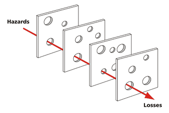
Sometimes this concept is referred to as the “Swiss Cheese Model.” I’ll quote from Wikipedia:

It likens human systems to multiple slices of swiss cheese, stacked side by side, in which the risk of a threat becoming a reality is mitigated by the differing layers and types of defenses which are “layered” behind each other. Therefore, in theory, lapses and weaknesses in one defense do not allow a risk to materialize, since other defenses also exist, to prevent a single point of failure. The model was originally formally propounded by Dante Orlandella and James T. Reason of the University of Manchester, and has since gained widespread acceptance. It is sometimes called the cumulative act effect.

To understand how this works in a functioning program, I want to point out how we recently addressed a single hazard in our program to show how many different ways we attempted to control it.


The hazard

 In IIAR’s upcoming standard 6 “Standard for Inspection, Testing, and Maintenance of Closed-Circuit Ammonia Refrigeration Systems” a hazard is identified and a prohibition is put in place to address that hazard:


5.6.3.4 Hot work such as the use of matches, lighters, sulfur sticks, torches, welding equipment, and similar portable devices shall be permitted except when charging is being performed and when oil or ammonia is being removed from the system.


The IIAR is recognizing that there is an increased likelihood of an Ammonia / Oil fire during charging operations and when oil / ammonia is being drained from the system. They are prohibiting Hot Work operations during these operations to remove potential ignition sources.


The Control(s)

You can make a (weak) case that simply referencing the RAGAGEP and inserting a single line in your Hot Work policy address the compliance requirement, but we’re going to need to do a lot more to make this prohibition a “real” thing in our actual operations.


Control Group #1: The Hot Work element

In the element Written Plan, we added two new “call-out’s” in the two places they are likely to be seen when planning Hot Work policies. First, in the section on Conducting Hot Work:


Second, in the section on Sulphur Stick use:


Third, in the Hot Work Permit itself, we modified the existing question on flammable atmospheres:


Control Group #2: The Operating & MI Procedures

All procedures that involve oil draining, ammonia charging and ammonia purging already point to the LEO (Line & Equipment Opening a.k.a. Line Break) written procedure. This makes our job a bit easier here, since we only have to modify our LEO rather than the dozens of procedures that might include this type of work.

We modified the traditional LEO “General Precautions section to place a check for Hot Work during an existing requirement to canvas the area for personnel that may be affected by the LEO:


In the more advanced, two-step “Pre-Plan and Permit” version of our LEO, we modified the “Pre-Plan Template” to include a warning:


In both versions of the LEO permit itself, we added an explicit check:


Closing Thoughts

This one small RAGAGEP change points to a single hazard – a hazard that we’re now trying to control in six different ways. Notice that we’ve made all these changes so they are popping up throughout the program:

  • In preparing policies for the associated work;
  • In the course of preparing for the work itself;
  • In the course of conducting the potentially hazardous operations.

This is critical because if we want to get the best “bang for our buck” in Process Safety, the safety portion has to be integrated into our actual processes on multiple levels.

Obviously, we’ll have to train on these changes to ensure that they’ll be effective. It’s quite possible that, after implementation, we’ll identify additional ways to prevent the hazard from being realized and will need to make further changes.

IIAR 6 – What do you need to know?

What is IIAR 6?

ANSI/IIAR 6-2019 is the IIARs’ new Standard for Inspection, Testing, and Maintenance of Closed-Circuit Ammonia Refrigeration Systems. To quote the forward from the public review:

This is a new standard intended to replace IIAR Bulletin No. 108 Guidelines for: Water Contamination in Ammonia Refrigeration Systems, IIAR Bulletin No. 109 Guidelines for: IIAR Minimum Safety Criteria for a Safe Ammonia Refrigeration System, IIAR Bulletin No. 110 Guidelines for: Start-Up, Inspection, and Maintenance of Ammonia Mechanical Refrigerating Systems, and IIAR Bulletin No. 116 Guidelines for: Avoiding Component Failure in Industrial Refrigeration Systems Caused by Abnormal Pressure or Shock. This new standard is intended to be a single source for the minimum requirements for ITM tasks for safe closed-circuit ammonia refrigeration systems.

Note: Design items pertaining to Bulletin No. 108 and Bulletin No. 116 are being considered to be incorporated in the next revision of IIAR 2, before these two bulletins are superseded.

When will it take effect?

Now that ANSI/IIAR 6-2019 has finished its Public Reviews, the end of this long journey is nearly over. Already approved by the IIAR Board of Directors  and ANSI, the new standard should be published around July 1st.

Once the new standard is officially published it comes into effect once YOU or the AHJ adopt it. Most model codes are expected to adopt it in their 2021 review cycles.

Why should I care about it now?

There are a few reasons:

  • The old combination of outdated and scattered bulletins was difficult to follow and wasn’t updated to deal properly with modern equipment. ANSI/IIAR 6-2019 has a more modern sensibility.
  • There’s really nothing in ANSI/IIAR 6-2019 you shouldn’t want to do – it’s all fairly sensible “good practice” advice.
  • There’s a slightly lower administrative / MI overhead following the new standard than the old bulletins.
  • I think – overall – that it’s easier to comply with ANSI/IIAR 6-2019 than the old combination of bulletins.


How would I go about ensuring compliance with IIAR 6?

You will have to thoroughly review ANSI/IIAR 6-2019 and perform a Gap Analysis between its requirements and your current PSM/RMP system. Pay special attention to:

  • Your Mechanical Integrity element, schedule, work orders (ITPMRs) and MI procedures.
  • Your SOPs to the extent that they deal with shutdowns, start-ups and turn-arounds.


What would such a Gap Analysis look like?

 If you are using my template system, the good news is that I’ve updated the ENTIRE system to be ANSI/IIAR 6-2019 compliant. Because this has been a LARGE project that’s taken a lot of time, all the new files have been given the same date code: 030219.. You can grab the updated templates on the Google Shared Drive. Some things like the Element Written Plans, ITPMRs are plug-and-play, but others like the MI-EL1, SOPs, etc. will have to be customized for your facility. If (when) you update your PSM/RMP system, don’t forget to implement your MOC procedure! Please note: ALL future template additions will include the ANSI/IIAR 6 compliant text that has been added.

Below is my list of implementation challenges, observations, and changes


Challenge #1: Section 5.5.1.3 Inspection & Test documentation

While I applaud the IIAR for pointing out the necessary requirements for a FUNCTIONALLY EFFECTIVE MI system, it’s a very real possibility that this section and its requirements will be interpreted to require this documentation IN THE MI system. That’s unrealistic for some of the information and experience has shown us that it’s likely unworkable in the field. Below is a table that shows the IIAR documentation requirements and how they are handled in the PSM system.

IIAR Cite

Requirement How it’s Handled
5.1.1.3.1 Date of the inspection or test. OSHA/EPA requirement already handled on ITPMR.
5.1.1.3.2 Name of the individual or individuals that performed the inspection or test. OSHA/EPA requirement already handled on ITPMR.
5.1.1.3.3 Serial number or other identifier of the equipment on which the inspection or test was performed. OSHA/EPA requirement already handled on ITPMR.
5.1.1.3.4 Description of the inspection or test performed. OSHA/EPA requirement already handled on ITPMR.
5.1.1.3.5 Recommended corrective action(s) for each deficiency identified. OSHA/EPA requirement already handled on ITPMR.
5.1.1.3.6 Description of corrective action(s) for each deficiency identified. OSHA/EPA requirement already handled on ITPMR.
5.1.1.3.7 Identification of each designated responsible person assigned and authorized to remedy each deficiency identified. OSHA/EPA requirement. Handled in the Management System master recommendation tracking form RT-1. NOT duplicating this information on MI docs.
5.1.1.3.8 Results based on the conditions at commencement of the inspection or test, including instrumentation readings. This is already covered in the ITMPR Corrective Actions, Recommended Actions & Comments section if implemented correctly.
5.1.1.3.9 Expected activation set points (+/-) including a functional description of the control logic. This information is already provided in the respective equipment RESOPs and system level ROSOPs. Since all our ITPMRs are used in conjunction with the SOPs this should be sufficient.
5.1.1.3.10 Results based on the conditions after completion of the inspection or test, including instrumentation readings. OSHA/EPA requirement already handled on ITPMR.
5.1.1.3.11 Expected completion date(s). OSHA/EPA requirement. Handled in the Management System master recommendation tracking form RT-1. This may be handled through a CMMS, but we’re NOT duplicating this information on our MI docs.
5.1.1.3.12 Actual completion date(s). OSHA/EPA requirement. Handled in the Management System master recommendation tracking form RT-1. This may be handled through a CMMS, but we’re NOT duplicating this information on our MI docs.


 Challenge #2: Section 5.2, Table 5.2

The IIAR is introducing the same concept here as I did last year with the “Acceptable Task Frequency Window.” I think their window is over-broad and would not be comfortable defending it without further engineering rationale. For example, they are giving a 1 month window on a quarterly task vs. my 14 days, a 2 month window on a semi-annual task vs. my 1 month window. I’m sticking with my more conservative window for now, but – as always – you are welcome to change yours.


Challenge #3: Section 5.2

The IIAR is rightly calling out the need to re-evaluate task frequency based on a history of deficiencies. I’ve incorporated some of their wording directly in the MI Implementation Policy: Mechanical Integrity Schedule as follows: Where a history of repeated deficiencies has been recorded, task frequencies / methods should be re-evaluated. This is usually triggered through the Incident Investigation element and managed through the MOC/PSSR element.

The IIAR is also stating “Where a history of fault-free operation has been recorded, the (ITM) task frequencies are permitted to be decreased.” I am not comfortable with incorporating this wording into the written plan as while it is not necessarily wrong it is extremely difficult to defend without providing significant engineering rationale. OSHA has published a lot of guidance saying the opposite of what the IIAR is saying here, and while I believe OSHA is wrong in their guidance, we should probably pick-and-choose your battles better than this.


Challenge #4: Section 5.3.6

 5.3.6.1 – This section implements a few new logs/documentation requirements, including the “Procedure for Communicating between shifts” that the CCPS has long recommended. Those using the COM-LOG (as outlined in the Employee Participation Written Plan) were already handling this well. To improve the system though, that section has been moved from the EP plan and placed in the RMP (Management System) Written Plan and renamed “Written Communication Log.”

5.3.6.2 requires documentation on secondary coolants. The ITPMR HX-90 & ITPMR HX-365 already does much of this but a new line adds “If any glycol was added / removed, record the type and amount.” While in this section, removed all the references to Glycol and replaced with Fluid so it can be used with Brine and Glycol systems.

5.3.6.3 requires documentation of the NH3 test records. The required information was added to a new ITPMR: ITPMR-NH3 and it was added to the MI-EL-1.

5.3.6.4 requires documentation of the addition / removal of any oil. Created a new log called OIL-LOG and updated all PU, PV & RC ITPMRS to include a reference to this log during oil addition/draining steps.

5.3.6.5 requires documentation of the lubrication type, quantity needed, and quantity used. Created a new log called the LUBE-LOG and updated all AU, HX, EC, RC & VENT ITPMRS to include a reference to this log during lubrication steps.

5.3.6.6 requires documentation of Relief Valves. I have no intention of creating a log for this as all the information should be in the PSI and whatever work order / ITPMR was used to replace the relief valve. To make this easier, I’ve included new text in the ITPMR-PRV-365 “If the relief valve is to be replaced, the new valve model number and pressure setting must be confirmed and recorded by TWO people before replacement to be considered a “Direct Replacement.” “In-Kind” and other types of replacements must be handled in accordance with the facility MOC policy.” I’ve also included signature boxes in that ITPMR line item.


Challenge #5: Section 5.3.7

This section deals with record retention requirements. The advice given here by the IIAR does not seem to reflect the RMP and PSM guidance given by the EPA and OSHA and has therefore been skipped. A careful reading of the informative appendix shows that the drafters of this document understood that MI documentation needs to be kept for the life of the process. In any case, we’re in a digital world so you can avoid the argument entirely if you scan the documents, put them on a cloud-based server, and recycle the paper.


Challenge #6: Section 5.4.2

This section replaces the old IIAR B110 5yr Independent Inspection. It includes qualifications & conflict-of-interest requirements. In the informative appendix, they’ve also buried a certification requirement. All these requirements have been added in the Mechanical Integrity Written Plan under the Implementation Policy: Five Year Independent MI Inspection. To make my customer’s lives easier, I’ve also included a Responsible Person certification page in my MI Report Template as well as a signed statement regarding conflict-of-interest signed by the Team Leader for my MI Inspections, PHA’s and Compliance Audits.


Challenge #7: Section 5.5.1

This section deals with calibration of the instruments used in tests and inspections. I have included similar requirements in the ROSOP-QA concerning gauges for a long time, but it’s often ignored. We need to re-emphasize this issue! The ROSOP QA Pressure Gauge section was renamed to Testing Instrument and reworded to cover the additional ANSI/IIAR 6-2019 requirements.

PSM Program / Template Changes: The entire template PSM/RMP program was altered to conform with ANSI/IIAR 6-2019. All changes made in the 030219 templates are outlined below:

ALL PSM / RMP Element Written Plan Changes

  • Moved Definitions from individual element Written Plans References and Definitions Section to a stand-alone document. The stand-alone definitions document was placed in the RMP / Management System binder / folder. The total list of definitions was expanded to cover much of the same ground as IIAR 1 – Definitions. Where the definitions I use varied from the IIAR significantly, I added the IIAR definitions with a “Per IIAR, …” at the end of the definition I’m using. Where IIAR definitions are used, they were updated to the most recent version of IIAR 1. Added the new ANSI/IIAR 6-2019 definitions to the stand-alone definitions document.


RMP / Management System Element Written Plan Changes

  • Moved Implementation Policy: Written Communication Log (COMLOG) from Employee Participation to this Plan. (Not specifically required by ANSI/IIAR 6-2019 but a good idea I’ve wanted to implement for a while)
  • Moved the content of Implementation Policy: PSM Meeting Notes from Employee Participation to this Plan. Also expanded this section to include some suggested agenda items for PSM Team Meetings. (Not specifically required by ANSI/IIAR 6-2019 but a good idea I’ve wanted to implement for a while)


EP PSM / RMP Element Written Plan Changes

  • Renamed Implementation Policy: Communication between Shifts (COMLOG) to Implementation Policy: Written Communication Log (COMLOG) and moved it to the RMP (Management System) Written Plan. (Not specifically required by ANSI/IIAR 6-2019 but a good idea I’ve wanted to implement for a while)
  • Moved content of Implementation Policy: PSM Meeting Notes to Implementation Policy: PSM Team Composition, Meeting Documentation and Agenda in the RMP (Management System) Written Plan. (Not specifically required by ANSI/IIAR 6-2019 but a good idea I’ve wanted to implement for a while)


HW PSM / RMP Element Written Plan Changes

  • Updated both versions of the template to include explicit statement on NOT performing Hot Work or using Sulphur Sticks during Charging, or when removing Oil / NH3 from the system. (IIAR 6 5.6.3.4)


 PSSR PSM / RMP Element Plan Changes

  • Updated ALL the PSSR forms (Word) to match the new 1yr ITPMRs. Maybe someday I’ll create the PDF forms again but it’s a lot of work and I’d rather we all work with the new ITPMRs to validate / field verify them before I expend that effort.
  • Added new ITR-LP-PSSR for non-ammonia Liquid Pumps


MI PSM / RMP Element Written Plan Changes


References and Definitions

  • Added ANSI/IIAR 6-2019 as a standard reference
  • Added IRC MI Guidebook as a standard reference


Implementation Policy: Mechanical Integrity Schedule

  • Slight change to first sentence to clarify that this policy is covering the Ammonia Refrigeration System to cover the same ground as IIAR 6 5.1.1
  • Added language concerning modifying the schedule based on a history of recorded deficiencies.
  • Added IIAR 6 5.2.3 language concerning daily tasks not being required during holidays/weekends.


Implementation Policy: Mechanical Integrity Task Documentation

  • Modified the Corrective Actions, Recommended Actions & Comments section to improve the explanation of what’s expected in the ITPMR forms to cover the same ground as IIAR 6 5.1.1.3.8


Implementation Policy: Access to MIPs and Manufacturer’s Equipment Manuals

  • Modified this section for clarity so that it clearly includes all Process Operators and refrigeration Contractors. Removed specific location wording. (IIAR 6 5.3.2)


MI-EL-1 Maintenance Schedule / Checklist Changes

  • Added a line for Generators / Standby power sources (IIAR 6 5.5.4)
  • Added a line for Ammonia Hoses (IIAR 6 11.1.4, 11.1.5)
  • Changed IIAR B110 references to ANSI/IIAR 6-2019
  • Added Filename / Template Revision to the bottom of the Checklist. (Not specifically required by ANSI/IIAR 6-2019 but a good idea I’ve wanted to implement for a while)


ITMPR Changes


ALL ITPMRS

  • Added color banding. Thanks Scott!
  • Re-organized tasks for more grouping.
  • Set ITPMT tables to repeat Header Row as several ITPMRs are now two pages
  • Standardized (hopefully) the formatting of the numbered / bulleted lists
  • Re-organized the catch-all sections at the end. These are now a little bit longer, but they seem to be easier to read / follow now. Thanks to Scott for the idea.
  • Incorporated some additional items from field feedback. Thanks Jeremiah, Scott & Victor!
  • Added new ITPMR-LP for non-ammonia Liquid Pumps


Note: none of the above are specifically required by ANSI/IIAR 6-2019 but I’ve wanted to implement them for a while.


ITMPR AHT-365, AHNT-365 (Ammonia Hoses)

  • New ITPMRs based on ANSI/IIAR 6-2019 Table 11.1.4 & 11.1.5 to cover Ammonia Hoses (Transfer and Non-Transfer)


ITMPR AC-30, AC-365 (Air Curtains)

  • Added Lube-LOG reference
  • Incorporated IIAR 6 Table 11.1.6 valve items into the annual ITPMRs


ITMPR AP-365 (Ammonia Pumps)

  • Added Lube-LOG reference
  • Incorporated IIAR 6 Table 7.1 items into the ITPMRs
  • Incorporated IIAR 6 Table 11.1.6 valve items into the ITPMRs


ITMPR AU-90, AU-365 (Air Units)

  • Added Lube-LOG reference
  • Incorporated IIAR 6 Table 9.1 items into the ITPMR
  • Incorporated IIAR 6 Table 11.1.6 valve items into the ITPMR


ITMPR DETECT-180 (NH3 Detectors)

  • Incorporated IIAR 6 Table 12.3 items into the ITPMR


ITMPR DT-90, DT-365 (Diffusion Tanks)

  • Reformatting / Renumbering for consistency with other ITPMRs.
  • Added leak / freeze protection checks


ITMPR EC-30, EC-90, EC-365, EC-SD (Evaporative Condensers)

  • Added Lube-LOG reference (EC-90, EC-365, EC-SD)
  • Renumbered EC-90 to EC-180 (MI-El-1, Checklist)
  • Incorporated IIAR 6 Table 8.1 items into the ITPMRs
  • Incorporated IIAR 6 Table 11.1.6 valve items into the ITPMRs


ITMPR HX-90, HX-365 (Heat Exchangers)

  • A new item “If any glycol was added / removed, record the type and amount.”
  • Added Lube-LOG reference
  • Replaced references to Glycol with Fluid so it can be used for Brine systems as well.
  • Incorporated IIAR 6 Table 11.1.6 valve items into the ITPMRs


ITMPR MI-5yr (5yr MI)

  • Incorporated new ANSI/IIAR 6-2019 requirements in the ITPMR


ITMPR MR-365 (Machine Room)

  • Incorporated ANSI/IIAR 6-2019 Table 12.2 items into the ITPMR


ITMPR NH3 (Ammonia)

  • New ITPMR based on IIAR 6 Table 15.1


ITMPR PIPE-365

  • Incorporated IIAR 6 Table 11.1 items into the ITPMRs
  • Incorporated IIAR 6 Table 11.1.6 valve items into the ITPMRs


ITMPR PRV-365 (Pressure Relief Valves)

  • Included new text in the ITPMR-PRV-365 “If the relief valve is to be replaced, the new valve model number and pressure setting must be confirmed and recorded by TWO people before replacement to be considered a “Direct Replacement.” “In-Kind” and other types of replacements must be handled in accordance with the facility MOC policy.” (Not specifically required by IIAR 6 but a good idea I’ve wanted to implement for a while)
  • Included verification signature boxes in the valve replacement ITPMR line item. (Not specifically required by IIAR 6 but a good idea I’ve wanted to implement for a while)
  • Incorporated IIAR 6 Table 11.1.6 valve items into the ITPMR
  • Incorporated IIAR 6 Table 13.1 items into the ITPMR


ITMPR PU-90, PU-365 (Purgers)

  • Combined Hansen and Parker into single ITPMR (Not specifically required by IIAR 6 but a good idea I’ve wanted to implement for a while)
  • Added Oil Drain line and OIL-LOG reference
  • Incorporated IIAR 6 Table 14.1 items into the ITPMRs
  • Incorporated IIAR 6 Table 11.1.6 valve items into the ITPMRs


ITMPR PV-90, PV-365 (Pressure Vessels)

  • Added OIL-LOG reference
  • Added note to “operating within limits” question on PV-365 to remind the user to check pressure and temperature
  • Incorporated IIAR 6 Table 10.1 daily items into the ITPMRs
  • Incorporated IIAR 6 Table 11.1.6 valve items into the ITPMRs


RC-30, RC-90, RC-365 (Refrigeration Compressors)

  • ITMPR Removed RC-30 (MI-El-1, Checklist)
  • Added check that setpoints are appropriate for connected vessels (RC-90, RC-365)
  • Added Lube-LOG reference (RC-90, RC-365)
  • Added OIL-LOG reference (RC-90, RC-365)
  • Incorporated IIAR 6 Table 6.1 items into the ITPMRs
  • Incorporated IIAR 6 Table 11.1.6 valve items into the ITPMR


ITMPR SS-7, SS-365 (Safety Showers)

  • Incorporated IIAR 6 Table 12.5 items into the ITPMRs


ITMPR VENT90, VENT365 (Machine Room Ventilation)

  • Added additional IIAR 2 checks to VENT-365
  • Incorporated IIAR 6 Table 12.1 items into the ITPMRs


SOP (RESOP & ROSOP) Template Changes

All

  • While leak-checking was already addressed to some degree, there was some room for improvement. A leak check reminder has been placed in the LEO Return to Service A leak check task has been placed in ALL equipment SOP steps that open Isolation Valves in the Normal Startup procedural section (IIAR 6 5.5.3)
  • Where it wasn’t already done, all Normal Startup steps re-arranged to ensure that we are opening the unit to the system starting with he lowest threat and working towards the greatest threat: suction -> DC -> hgd -> liquid (Not specifically required by IIAR 6 but a good idea I’ve wanted to implement for a while)
  • For ALL Equipment RESOPS:
    • Slightly reworded Emergency Shutdown section to make it simpler. (Not specifically required by IIAR 6 but a good idea I’ve wanted to implement for a while)
    • Removed any specific MI steps from the Maintenance sections. We’re simply kicking it to the MI-El1, equipment-specific ITPMR’s and IOM’s. (Not specifically required by IIAR 6 but a good idea I’ve wanted to implement for a while)


ROSOP LEO – Line & Equipment Opening

  • Added leak check reminder in Return to Service section.


ROSOP SWT – System Walkthrough

  • Incorporated all ANSI/IIAR 6-2019 tables daily / weekly items into the ROSOP
  • Changed “Engine Room” to “Machine Room” everywhere I could find it! (Not specifically required by IIAR 6 but a good idea I’ve wanted to implement for a while)
  • Harmonized text between the RESOP “Monitor Normal Operations” sections and this document. (Not specifically required by IIAR 6 but a good idea I’ve wanted to implement for a while)
  • Added Autopurgers to Machine Room section


ROSOP QA – Quality Assurance

  • Added a section on Ice Accumulation (IIAR 6 5.6.8)
  • Updated Vessel & Pipe sections to include new guidance on corrosion. (IIAR 6 10.1.1-2)
  • Updated Pipe section to include new guidance on allowable thickness, Table A.11.1.1.3.1 Piping Sizes, Schedules, and Thicknesses (IIAR 6 A.11.1.1.3.1)
  • Updated Vessel section to include new guidance on nameplates. (IIAR 6 10.1.4)
  • Renamed Pressure Gauge section to Testing Instrument and provided additional ANSI/IIAR 6-2019 requirements. (IIAR 6 5.5)


RESOP AP – Autopurger

  • Incorporated Table 14.1 (autopurgers) daily items into the Monitor Normal Operations Section and harmonized that section with the ROSOP SWT Walkthrough procedure.


RESOP AU – Air Unit

  • Incorporated Table 9.1 (evaporators) daily items into the Monitor Normal Operations Section and harmonized that section with the ROSOP SWT Walkthrough procedure.


RESOP C – Compressors

  • Incorporated Table 6.1 (compressors) daily items into the Monitor Normal Operations Section and harmonized that section with the ROSOP SWT Walkthrough procedure.


RESOP EC – Condensers

  • Incorporated Table 8.1 (condensers) daily items into the Monitor Normal Operations Section and harmonized that section with the ROSOP SWT Walkthrough procedure.


RESOP HPRTSR – Non-recirculating Vessels

  • Incorporated Table 10.1 (vessels) daily items into the Monitor Normal Operations Section and harmonized that section with the ROSOP SWT Walkthrough procedure.


RESOP HTR – Recirculating Vessels

  • Incorporated Table 7.1 (pumps) daily items into the Monitor Normal Operations Section and harmonized that section with the ROSOP SWT Walkthrough procedure.
  • Incorporated Table 10.1 (vessels) daily items into the Monitor Normal Operations Section.


RESOP HX – Heat Exchangers

  • Incorporated Table 9.1 (evaporators) daily items into the Monitor Normal Operations Section and harmonized that section with the ROSOP SWT Walkthrough procedure.


IIAR 5 updates out for Public Review

The IIAR has announced the Second (2nd) Public Review of BSR/IIAR 5-201x, Startup of Closed-Circuit Ammonia Refrigeration Systems. This is another “partial” review in that it only shows the changed text in context, not the whole standard. I can already see that the PSM-related section in 5.4.1 is tying itself in knots trying to avoid using the term “review the PHA” like the new IIAR Compliance Guidelines draft will. Your review of these documents – and your subsequent comments – help guide our industry.


March 22nd, 2019
To: IIAR Members
Re: Second (2nd) Public Review of BSR/IIAR 5-201x, Startup of Closed-Circuit Ammonia Refrigeration Systems

A second (2nd) public review of draft standard BSR/IIAR 5-201x, Startup of Closed-Circuit Ammonia Refrigeration Systems is now open. The International Institute of Ammonia Refrigeration (IIAR) invites you to make comments on the draft standard. Substantive changes resulting from this public review will also be provided for comment in a future public review if necessary.

BSR/IIAR 5-201x, defines the minimum requirements for startup of closed-circuit ammonia refrigeration systems. It presupposes that the persons who use the document have a working knowledge of the functionality of an ammonia refrigeration system(s) and basic ammonia refrigeration practices and principles. This standard is intended for those who startup closed-circuit ammonia refrigeration systems. This standard shall apply only to stationary closed-circuit refrigeration systems utilizing ammonia as the refrigerant. It supplements existing general refrigeration standards issued by IIAR and other organizations such as ASHRAE, ASME, and ANSI. It is not intended to supplant existing safety codes (e.g., model mechanical or fire codes).

IIAR has designated the draft standard as BSR/IIAR 5-201x. Upon approval by the ANSI Board of Standards Review, the standard will receive a different name that reflects this approval date.

We invite you to participate in the second (2nd) public review of BSR/IIAR 5-201x. IIAR will use the American National Standards Institute (ANSI) procedures to develop evidence of consensus among affected parties. ANSI’s role in the revision process is to establish and enforce standards of openness, balance, due process, and harmonization with other American and International Standards. IIAR is the ANSI-accredited standards developer for BSR/IIAR 5-201x, and is responsible for the technical content of the standard.

This site includes links to the following attachments:


The 30-day public review period will be from March 22nd, 2019 through April 21st, 2019. Comments are due no later than 5:00 pm Eastern Standard Time (EST) on April 21st, 2019.

Thank you for your interest in the public review of BSR/IIAR 5-201x, Startup of Closed-Circuit Ammonia Refrigeration Systems.

« Older posts